Digital Principles and Computer Organization: Chapter 3: Computer System
Basic Structure and Functional Units of a Computer
1. Structural Components of a Computer 2. Functional Units: Input Unit, Memory Unit, Arithmetic and Logic Unit, Output Unit, Control Unit 3. Interconnection of Components. Single Bus Structure, Multiple Bus Hierarchies. Questions : 1. Define the term CPU. Why is it called the brain of the computer? 2. Explain the structure of a computer with the help of a neat diagram. 3. Explain the main components of the CPU with a neat block diagram. 4. What are the functions of the Arithmetic and Logic Unit (ALU)? 5. State the role of the Control Unit (CU) in a computer. 6. What is the purpose of registers in the CPU? Give one example of a register. 7. Describe the function of the memory unit. 8. Explain different functional units of a digital computer. 9. What is a stored program concept? Explain the functional units of a stored program digital computer, along with a block diagram. 10. What is a system bus? 11. Explain the three types of system buses. 12. Explain why only two units can communicate at a time in a single bus structure. 13. What is the role of multiplexed address/data lines in a single bus structure, and why are latches required? 14. List two limitations of using a single bus structure in large computer systems. 15. Why do modern computer systems use multiple bus hierarchies instead of a single bus? 16. Explain the high-speed bus configuration.
Digital Principles and Computer Organization:
Chapter 3: Computer System
Basic Structure and
Functional Units of a Computer
•
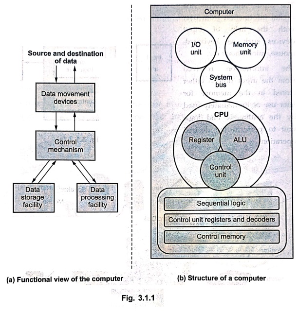
A computer structure refers to the
way in which different computer components are interconnected and organized. It shows the arrangement of units
such as the CPU, memory, input/output devices and system buses.
•
A computer function, on the other
hand, describes the operations performed
by each component as a part of the overall system. In other words,
structure explains "how.components are arranged," while function
explains "what each component does."
•
Every computer performs four basic functions :
1. Data processing –
Performing arithmetic and logical operations.
2. Data storage –
Holding data and instructions temporarily or permanently.
3. Data movement –
Transferring data between the computer and the outside world.
4. Control –
Directing and coordinating the activities of all parts of the system.
1. Structural Components of a Computer
• Central Processing
Unit (CPU)
■
Often called the brain of the computer.
■
Controls overall operations and performs data processing.
■
Major parts : Arithmetic and Logic Unit (ALU), Control Unit (CU) and Registers.
• Main memory
■
Stores data and instructions that are currently in use.
■
Provides fast, temporary storage directly accessible by the CPU.
• Input/Output (I/O)
devices
■
Enable interaction with the external environment.
■
Input examples : Keyboard, mouse, scanner.
■
Output examples : Monitor, printer, speakers.
• System
interconnection (Buses)
■
Provides a pathway for communication among CPU, memory and I/O devices.
■
Includes : Data bus, Address bus, and Control bus.
2. Functional Unitssive
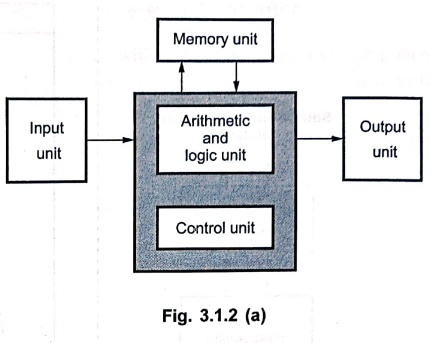
• The
computer consists of five functionally independent units:
■
Input
■
Memory
■
Arithmetic and logic
■
Output and
■
Control units.
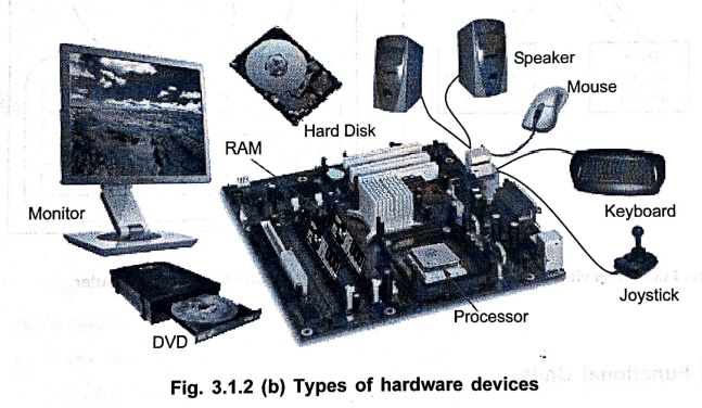
• Fig.
3.1.2 (a) and (b) show these five functional units of a computer and its
physical locations in the computer.
• The
input unit accepts the digital information from user with the help of input devices
such as keyboard, mouse, microphone etc.
• The
information received from the input unit is either stored in the memory for
later use or immediately used by the arithmetic and logic unit to perform the
desired operations.
• The
program stored in the memory decides the processing steps and the processed
output is sent to the user with the help of output devices or it is stored in
the memory for later reference.
• All
the above mentioned activities are co–ordinated and controlled by the control unit.
•
The arithmetic and logic unit in conjunction with control unit is commonly
called Central Processing Unit (CPU).
1. Input Unit
• A
computer accepts a digitally coded information through input unit using input devices.
• The
most commonly used input devices are keyboard and mouse.
• The
keyboard is used for entering text and numeric information.
•
Mouse is used to position the screen cursor and thereby enter the information
by selecting option.
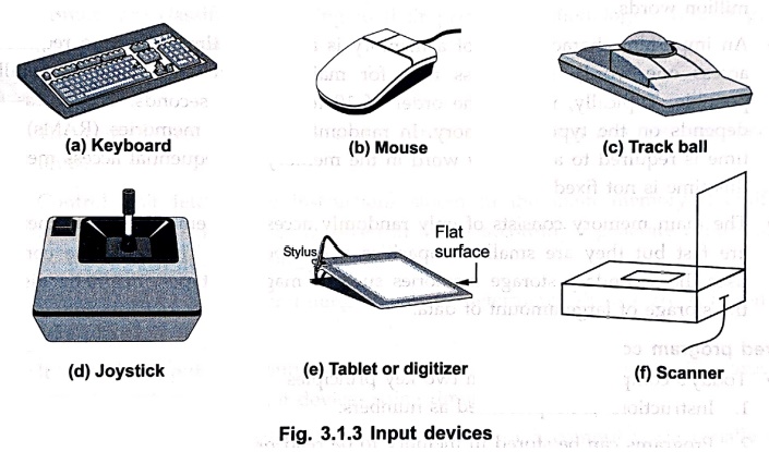
• Apart
from keyboard and mouse there are many other input devices are available, which
include joysticks, trackball, spaceball, digitizers and scanners.
2. Memory Unit
• The
memory unit is used to store programs and data.
• Usually,
two types of memory devices are used to form a memory unit : primary storage memory device and secondary
storage memory device.
• The
primary memory, commonly called main
memory is a fast memory used for the storage of programs and active data
(the data currently in process).
•
The main memory is a semiconductor memory.
•
It consists of a large number of semiconductor storage cells, each capable of
storing one bit of information.
• These
cells are read or written by the central processing unit in a group of fixed
size called word.
• The
main memory is organized such that the contents of one word, containing n bits,
can be stored or retrieved in one write or read operation, respectively.
• To
access data from a particular word from main memory each word in the main
memory has a distinct address. This
allows to access any word from the main memory by specifying corresponding
address.
• The
number of bits in each word is referred to as the word length of the computer. Typically, the word length varies from
8 to 64 bits.
•
The number of such words in the main memory decides the size of memory or capacity
of the memory.
•
The size of computer main memory varies from few million words to tens of
million words.
•
An important characteristics of a memory is an access time (the time required to access one word). The access time
for main memory should be as small as possible. Typically, it is of the order
to 100 nanoseconds. The access time depends on the type of memory. In randomly
accessed memories (RAMs), fixed time is required to access any word in the
memory. In sequential access memories this time is not fixed.
• The
main memory consists of only randomly accessed memories. These memories are
fast but they are small in capacities and expensive. Therefore, the computer
uses the secondary storage memories such as magnetic tapes, magnetic disks for
the storage of large amount of data.
Stored program concept
•
Today's computer are built on two key principles
1.
Instructions are represented as numbers.
2.
Programs can be stored in memory to be read or written just like numbers.
•
These principles lead to the stored–program concept.
• According
to stored–program concept, memory can contain the program (source www.code),
the corresponding compiled machine code, editor program and even the compiler
that generated the machine code.
3. Arithmetic and Logic Unit
• The
arithmetic and logic unit (ALU) is responsible for performing arithmetic
operations such as add, subtract, division and multiplication and logical
operations such as ANDing, ORing, Inverting etc.
•
To perform these operations, operands from the main memory are brought into the
high speed storage elements called
registers of the processor.
• Each
register can store one word of data and they are used to store frequently used
operands.
• After
performing operation, the result is either stored in the register or memory
location.
4. Output Unit
The
output unit sends the processed results to the user using output devices such
as video monitor, printer, plotter, etc.
•
The video monitors display the output on the CRT screen whereas printers and
plotters give the hard–copy output.
• Printers
are classified according to their printing methodology : Impact printers and non–impact
printers.
5. Control Unit
• The
control unit co–ordinates and controls the activities amongst the functional
units.
• Control
unit fetches the instructions stored in the main memory, identify the
operations and the devices involved in it and accordingly generate control
signals to execute the desired operations.
•
It uses control signals or timing signals to determine when a given action is
to take place.
• It controls input and output operations,
data transfers between the processor, memory and input/output devices using
timing signals.
• The
control and the arithmetic and logic units of a computer are usually many times
faster than other devices connected to a computer system. This enables them ou
to control a number of external input/output devices.
3. Interconnection of Components
• The
interconnection of components in a computer system is handled by a set of
communication pathways known as a System
Bus.
• It
is the primary communication pathway that connects the main components of a
computer : the CPU (Central
Processing Unit), the Memoryd Unit, and
I/O (Input/Output) devices. It acts
as a shared highway for data, addresses, and control signals, enabling all
these components to work together seamlessly.
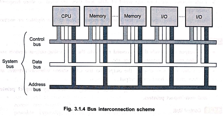
• The
system bus is not a single bus but rather a collection of three distinct buses, each with a specific role :
1. Data bus
■
A bidirectional pathway that carries
the actual data being transferred between the CPU, memory and I/O devices.
■
When the CPU reads data, it flows from memory (or I/O device) to the CPU. When
the CPU writes data, it flows from the CPU to memory (or I/O device).
■
The width of the data bus (e.g., 8,
16, 32, or 64 bits) determines how many bits can be transferred simultaneously.
A wider data bus allows more information to move in a single operation,
improving performance.
2. Address bus
■
A unidirectional pathway used to
specify the address of the memory location or I/O device that the CPU wants to
access.
■
The CPU places the desired address on the address bus, and the memory or I/O
device with that address responds.
■
The width of the address bus
determines the maximum addressable memory. For instance, a 32–bit address bus
can directly access 232 = 4 GB of memory.
3. Control bus
■
A set of lines that carries control
signals required to manage and coordinate all operations of the system bus.
■
Examples of control signals include :
➤ Memory read –
Instructs memory to place data on the data bus.
➤ Memory write –
Instructs memory to store data from the data bus.
➤ I/O read –
Reads data from an input device.
➤ I/O write –
Sends data to an output device.
■ The control bus ensures proper timing and
prevents conflicts, so only one device drives the bus at a time.
1. Single Bus Structure
•
In a computer system, the interconnection between the CPU, memory, and
input/output devices can be achieved in different ways. One common method is
the single bus structure.
•
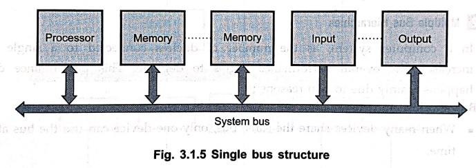
In this structure, all components are connected to a common communication path
called the system bus. The system bus
combines the address bus, data bus
and control bus into a single bus,
as shown in Fig. 3.1.5.
Working of a single bus structure
•
Since all units share the same bus, only two
units can communicate at a time (for example, CPU to memory, or CPU to
I/O).
• Bus control lines
are used to manage access when multiple units request the bus simultaneously.
•
Multiplexed address/data lines are often used to reduce the number of pins. In
such cases :
■
During the first part of the cycle, the address is placed on the bus.
■
In the second part, the same lines are used for data transfer.
■
To handle this, latches are required
to store the address.
Advantages of single bus structure
1. Low cost :
Since all devices share a common bus, hardware requirement are reduced.
2. Flexibility :
Easy to attach additional peripheral devices.
3. Simplicity :
Suitable for small systems where control logic is not very complex.
Limitations of single bus structure
1. Limited
communication : Only one pair of devices can use the
bus at a time, creating a bottleneck.
2. Bus arbitration
required : Additional control logic is necessary to manage
multiple requests for the bus.
3. Performance issues
in large systems : With many devices connected, data
transfer speed decreases due to
contention.
4. Signal quality :
Large systems require bus drivers and receivers to maintain signal strength and
timing.
2. Multiple Bus Hierarchies
•
In a computer system, as the number of devices connected to a single bus
increases, the overall performance begins to degrade. This performance drop
happens mainly due to two reasons :
1. Bus sharing and propagation delays:
■
When many devices share the same bus, only one device can use the bus at a time
■
The sharing process requires coordination, and when control of the bus is
frequently transferred from one device to another, propagation delays become noticeable.
■
These delays reduce the efficiency of the computer system.
2. Bus bottleneck :
■
As the combined data transfer demands of devices approach the maximum capacity
of the bus, the bus becomes a bottleneck.
■
To overcome this, either the bus speed must be increased, or the bus must be
made wider (more data lines).
■
However, with modern high–speed devices like video controllers and network
interfaces, a single bus cannot practically handle all the traffic.
Need for multiple bus hierarchies
•
Because of these limitations, modern computer systems use multiple buses organized in a hierarchical
structure. This structure reduces contention on a single bus and improves
overall system performance.
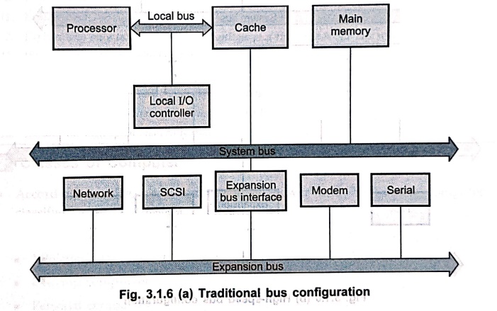
Traditional bus configuration
•
Consists of three types of buses:
1. Local bus –
Connects the CPU to cache and memory for high–speed access.
2. System bus –
Connects the CPU, main memory and I/O subsystem.
3. Expanded bus – Provides
connections for additional peripheral devices (e.g., printers, disk drives).
•
This structure reduces the load on a single bus by distributing data transfers
across multiple buses.
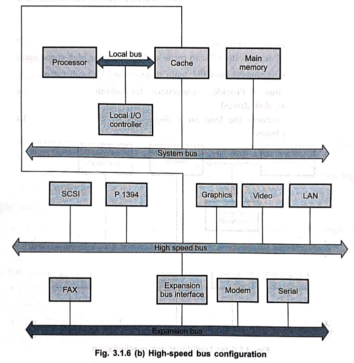
High–speed bus configuration
•
In addition to the local, system,
and expanded buses, a high–speed bus is introduced.
•
The cache controller is connected to
this high–speed bus.
•
It supports devices with very high data transfer requirements, such as :
■
High–speed LANs (e.g., Fiber Distributed Data Interface – FDDI).
■
Video and graphics workstation controllers.
■
High–performance I/O controllers (e.g., SCSI, IEEE P1394/FireWire).
•
By isolating high–bandwidth devices on a dedicated high–speed bus, the
superformance of the overall system is significantly improved.
Advantages of multiple bus hierarchies
1. Reduced bottlenecks
:
Different buses handle different types of data transfer, preventing congestion.
2. Improved performance
:
High–speed devices can operate on dedicated buses without affecting slower
devices.
3. Scalability :
New devices can be added to specific buses without overloading the main system
bus.
4. Flexibility :
Allows integration of diverse devices with varying speed requirements.
Review Questions
1. Define the term
CPU. Why is it called the brain of the computer?
2. Explain the
structure of a computer with the help of a neat diagram.
3. Explain the main
components of the CPU with a neat block diagram.
4. What are the
functions of the Arithmetic and Logic Unit (ALU)?
5. State the role of
the Control Unit (CU) in a computer.
6. What is the purpose
of registers in the CPU? Give one example of a register.
7. Describe the
function of the memory unit.
8. Explain different
functional units of a digital computer.
9. What is a stored
program concept? Explain the functional units of a stored program digital
computer, along with a block diagram.
10. What is a system
bus?
11. Explain the three
types of system buses.
12. Explain why only
two units can communicate at a time in a single bus structure.
13. What is the role
of multiplexed address/data lines in a single bus structure, and why are
latches required?
14. List two
limitations of using a single bus structure in large computer systems.
15. Why do modern
computer systems use multiple bus hierarchies instead of a single bus?
16. Explain the high–speed
bus configuration.
Digital Principles and Computer Organization: Chapter 3: Computer System : Tag: : - Basic Structure and Functional Units of a Computer
Digital Principles and Computer Organization: Chapter 3: Computer System
Under Subject

Digital Principles and Computer Organization
CS25C06 2nd Semester AIDS, CSE, IT, CSE(CY) Dept | 2025 Regulation | 2nd Semester 2025 Regulation
Related Subjects

English Essentials II
EN25C02 2nd Semester | 2025 Regulation | 2nd Semester 2025 Regulation

Tamils and Technology தமிழர்களும் தொழில்நுட்பமும்
UC25H02 2nd Semester | 2025 Regulation | 2nd Semester 2025 Regulation

Linear Algebra
MA25C02 2nd Semester | 2025 Regulation

Applied Physics (CSIE) II
PH25C03 2nd Semester AIDS, CSE, IT, CSE(CY) Dept | 2025 Regulation | 2nd Semester 2025 Regulation
Digital Principles and Computer Organization
CS25C06 2nd Semester AIDS, CSE, IT, CSE(CY) Dept | 2025 Regulation | 2nd Semester 2025 Regulation

Basic Electrical and Electronics Engineering
EE25C01 2nd Semester | 2025 Regulation | 2nd Semester 2025 Regulation

Python for Data Science
AD25201 2nd Semester AIDS Dept | 2025 Regulation | 2nd Semester 2025 Regulation

Re-Engineering for Innovation
ME25C05 2nd Semester | 2025 Regulation | 2nd Semester 2025 Regulation

Python for Data Science - Laboratory
AD25201 2nd Semester AIDS Dept | 2025 Regulation | 2nd Semester 2025 Regulation