Digital Principles and Computer Organization: Chapter 3: Computer System
Instruction Execution Cycle
Questions : 1. Explain the instruction cycle. 2. Draw the instruction cycle state diagram. 3. Explain the indirect cycle. 4. Explain the data flow during fetch and decode cycle. 5. Explain the data flow during indirect and interrupt cycle. 6. Explain instruction cycle states of a processor with suitable diagram.
Instruction Execution
Cycle
•
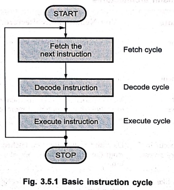
An instruction cycle involves three subcycles,
■
Fetch : The fetch phase reads the
next instruction from memory into the CPU.
■ Decode : The decode phase interprets
the opcode by decoding it.
■
Execute : The execute phase performs
the indicated operation.
•
Fig. 3.5.1 shows the basic instruction cycle. (See Fig. 3.5.1 on next page).
•
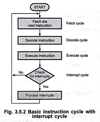
Actually, processor checks for valid interrupt request after each instruction
cycle. If any valid interrupt request is present, Processor saves the current
process state and services the interrupt. Servicing the interrupt means
executing interrupt service routine. After completing it, processor starts the
new instruction cycle from where it has been interrupted. Fig. 3.5.2 shows this
instruction cycle with interrupt cycle.
The indirect cycle
•
If the operands on which the instruction works are present within the processor–registers,
a memory access is not required. But if the execution of an instruction
involves one or more operands in memory, each requires a memory access.
•
For fetching the indirect addresses, one or more instruction sub cycles are
required.
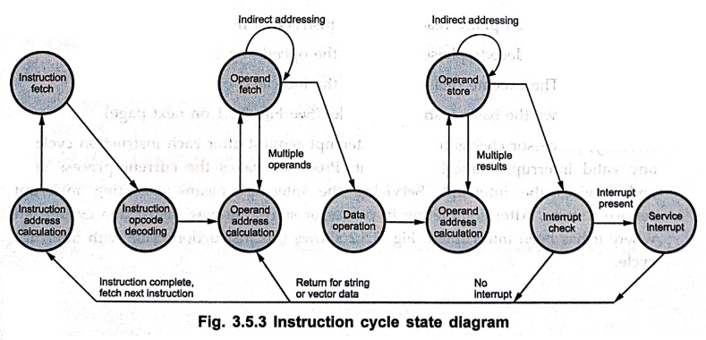
• After fetching the instruction, it is decoded and if any indirect addressing is involved, the required operands are fetched using indirect addressing.
•
Also, after performing the operation on the operands according to the opcode, a
similar process may be needed to store the result in memory.
•
Following execution, interrupted processing may be required before fetching then
instruction. The same process can be viewed as shown in Fig. 3.5.3.
•
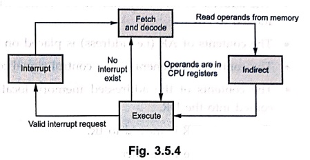
Combining fetch and decode cycle, the instruction cycle with indirect cycle is
the Fig. 3.5.4.
1 Data Flow
•
We have seen the subcycles involved in the complete instruction cycle. The instruction
cycle involves events depending on the design of the CPU. To study art these
events, let us assume different units available in CPU as Program Counter (PC),
Address Register (AR), Data Register (DR), an Instruction Register (IR), Instruction
Decoder (ID) and control unit. Let us study different events involved in
instruction cycle using these units in CPU.
Fetch cycle
•
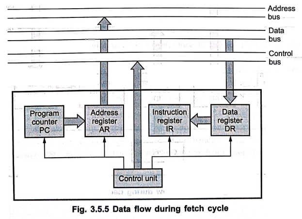
During the fetch cycle an instruction opcode is read from memory. The following
sequence of operations take place during this cycle.
•
The address of an instruction to be fetched from memory is in PC. This address
is moved to AR.
•
The contents of AR (i.e. address) is placed on the address bus.
•
The control unit generates the control signal to read the contents of the
memory.
•
The contents of the addressed memory location are placed on the data bus and
copied into the DR.
•
The data in DR is moved to IR.
•
Meanwhile, the PC is incremented by one for pointing the next data in memory.
Decode cycle
•
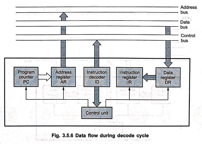
During decode cycle, the IR contents (i.e. opcode) are decoded by ID. During
decoding operation, it is determined that the operands are present within
registers of CPU or indirect addressing is required. For indirect addressing,
indirect cycle is performed. The DR contains the address reference. This is
transferred to the AR.The control unit generates the control signal to read the
desired address of the operand into DR as shown in Fig. 3.5.6.
Indirect cycle
•
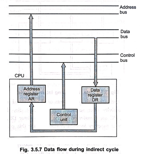
Once the decode cycle is over, the control unit determines if it contains an
operand specifier using indirect addressing. If so, an indirect cycle is
performed as shown in Fig. 3.5.7.
•
The data register, DR contains address reference in the form of some bits in
it. It is transferred to address register, AR. Then the control unit generates
the control signal to read the contents of the memory. These contents of the
memory are nothing but the desired address of the operand which is stored data
register.
Execute cycle
•
The fetch, decode and indirect cycles are simple and predictable. However, the
execute cycle takes many forms. This form depends on the contents of IR. During
execute cycle, the actual operation is performed. This cycle may involve transferring
data among registers, read or write from memory or I/O, and/or arithmetic or
logic operation of the ALU.
Interrupt cycle
•
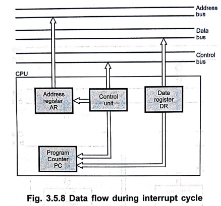
Fig. 3.5.8 shows the data flow during interrupt cycle.
•
During interrupt cycle, the current contents of PC are saved so that the CPU
can resume normal activity after servicing the interrupt. So, the contents of
the program counter, PC are transferred to the data register DR, to be written
into memory. The special memory location is reserved for this purpose. For
example, stack.
•
This memory location or address is loaded into the address register, AR from
the control unit. It might, for example, be a stack pointer. The interrupt
service routine address is loaded into the PC. So, the next instruction cycle
will begin by fetching the first instruction from the interrupt service
routine.
Review Questions
1. Explain the
instruction cycle.
2. Draw the
instruction cycle state diagram.
3. Explain the
indirect cycle.
4. Explain the data
flow during fetch and decode cycle.
5. Explain the data
flow during indirect and interrupt cycle.
6. Explain instruction
cycle states of a processor with suitable diagram.
Digital Principles and Computer Organization: Chapter 3: Computer System : Tag: : - Instruction Execution Cycle
Digital Principles and Computer Organization: Chapter 3: Computer System
Under Subject

Digital Principles and Computer Organization
CS25C06 2nd Semester AIDS, CSE, IT, CSE(CY) Dept | 2025 Regulation | 2nd Semester 2025 Regulation
Related Subjects

English Essentials II
EN25C02 2nd Semester | 2025 Regulation | 2nd Semester 2025 Regulation

Tamils and Technology தமிழர்களும் தொழில்நுட்பமும்
UC25H02 2nd Semester | 2025 Regulation | 2nd Semester 2025 Regulation

Linear Algebra
MA25C02 2nd Semester | 2025 Regulation

Applied Physics (CSIE) II
PH25C03 2nd Semester AIDS, CSE, IT, CSE(CY) Dept | 2025 Regulation | 2nd Semester 2025 Regulation
Digital Principles and Computer Organization
CS25C06 2nd Semester AIDS, CSE, IT, CSE(CY) Dept | 2025 Regulation | 2nd Semester 2025 Regulation

Basic Electrical and Electronics Engineering
EE25C01 2nd Semester | 2025 Regulation | 2nd Semester 2025 Regulation

Python for Data Science
AD25201 2nd Semester AIDS Dept | 2025 Regulation | 2nd Semester 2025 Regulation

Re-Engineering for Innovation
ME25C05 2nd Semester | 2025 Regulation | 2nd Semester 2025 Regulation

Python for Data Science - Laboratory
AD25201 2nd Semester AIDS Dept | 2025 Regulation | 2nd Semester 2025 Regulation