Digital Principles and Computer Organization: Chapter 3: Computer System
Von Neumann Architecture
Structure, Instructions Supported
Questions: 1. Draw and explain the Von Neumann architecture. 2. Draw Von Neumann architecture and explain function of registers in it. stab grilirw 3. Explain IAS (Von Neumann) architecture with the help of neat diagram and list the instructions supported by IAS computer.
Von Neumann
Architecture
•
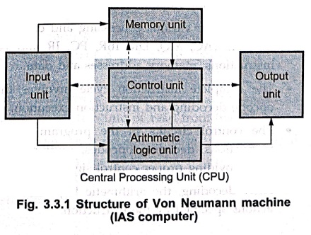
Fig. 3.3.1 shows the general structure of a Von Neumann machine (IAS computer).
•
It consists of five basic units whose functions can go be summarized as
follows:
■
The input unit transmits data and
instructions from the outside world to machine. It is operated by, control
unit.
■
The memory unit stores both, data
and instructions.
■
The arithmetic–logic unit (ALU)
performs arithmetic and logical operations.
■
The control unit fetches and
interprets the instructions in memory and causes them to be executed.
■
The output unit transmits final
results and messages to the outside world.
•
In the original IAS machine (Von Neumann machine), memory unit consists of 4096
storage locations of 40 bits each, referred to as words. These memory locations
are used to store data as well as instructions.
Features of Von Neumann model
• It uses stored
program concept. The program (instructions) and data are stored in a single
read–write memory.
• The contents of read–write
memory are addressable by location, without regard to the type of data
contained there.
• Execution of instructions
occurs in a sequential manner (unless explicitly modified) from one instruction
to the next.
• Von Neumann
bottleneck : Because of the stored program
architecture of Von–Neumann machine, the processor performance is tightly bound
to the memory performance. That is, since we need to access memory at least
once per cycle to read an instruction, the processor can only operate as fast
as the memory. This is sometimes known as the Von Neumann bottleneck or memory
wall.
1. Detail Structure of IAS / Von Neumann Machine
•
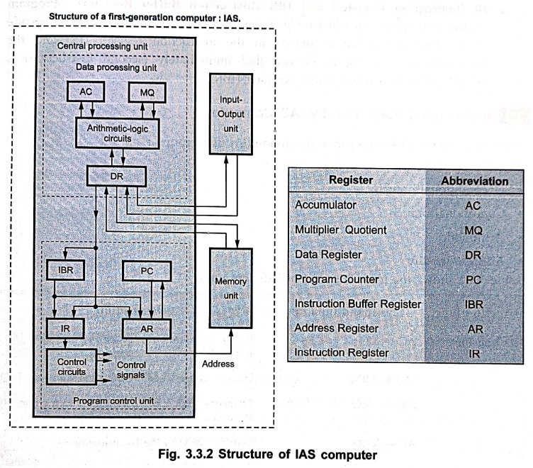
Fig. 3.3.2 shows detail structure of IAS computer.
•
It consists of various processing and control units, along with a set of high
speed registers (AC, MQ, DR, IBR, PC, IR and AR). These registers are used to
store instructions, memory addresses and data.
•
The complete instruction cycle involves three operations : Instruction
fetching, opcode decoding and instruction execution.
•
The control circuits in the program control unit are responsible for fetching
instructions, decoding opcodes, routing information correctly through the
system and providing proper control signals for Central Processing Unit (CPU)
actions.
•
After decoding, the arithmetic logic circuits of the data processing unit
perform actions specified by the instruction.
•
An electronic clock circuit (not shown in the Fig. 3.3.2) is used to generate
the basic timing signals to synchronize the operation of the different parts of
the system.
•
The functioning of different registers is as given below :
■
PC (Program Counter) : It is an
address register. It is used to store the address of the next instruction to be
executed and hence also referred to as instruction address register.
■
AR (Address Register) : It is a 12–bit
address register. It is used to specify the address in memory of the word to be
written into or read from the DR.
■
DR (Data Register) : It is a 40–bit
register. It is used to store any 40–bit word. A word transfer can take place
between the 40–bit data register DR of the CPU and any memory location. The DR
may be used to store an operand during the execution of an instruction.
■ AC (Accumulator) and
MQ (Multiplier–Quotient) : These are two 40–bit registers
used for the temporary storage of operands and results.
■
IR (Instruction Register) and IBR
(Instruction Buffer Register) : Program control unit fetches two
instructions simultaneously from memory. The opcode of the first instruction is
placed in the instruction register (IR) and the instruction that is not to be
executed immediately (second instruction) is placed in the Instruction Buffer
Register (IBR).
2. Instructions Supported by IAS Computer
The
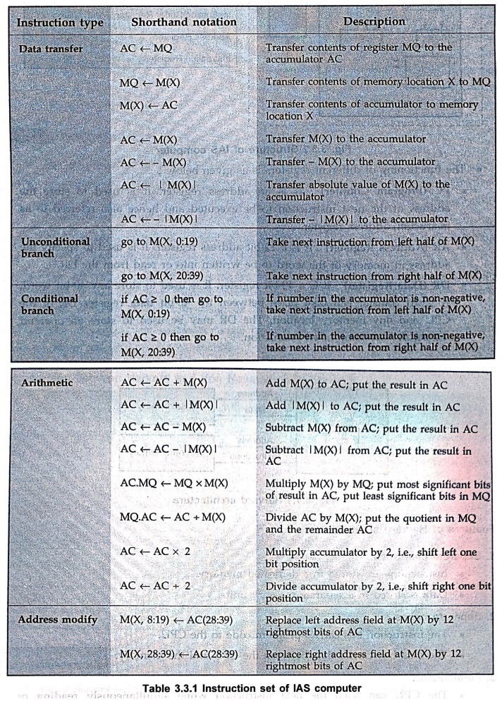
instructions of IAS computer are divided in five groups :
•
Data transfer
•
Unconditional branch
•
Conditional branch
•
Arithmetic
•
Address modify
Table
3.3.1 shows the instruction set of IAS computer.
Review Questions
1. Draw and explain
the Von Neumann architecture.
2. Draw Von Neumann
architecture and explain function of registers in it. stab grilirw
3. Explain IAS (Von
Neumann) architecture with the help of neat diagram and list the instructions
supported by IAS computer.
Digital Principles and Computer Organization: Chapter 3: Computer System : Tag: : Structure, Instructions Supported - Von Neumann Architecture
Digital Principles and Computer Organization: Chapter 3: Computer System
Under Subject

Digital Principles and Computer Organization
CS25C06 2nd Semester AIDS, CSE, IT, CSE(CY) Dept | 2025 Regulation | 2nd Semester 2025 Regulation
Related Subjects

English Essentials II
EN25C02 2nd Semester | 2025 Regulation | 2nd Semester 2025 Regulation

Tamils and Technology தமிழர்களும் தொழில்நுட்பமும்
UC25H02 2nd Semester | 2025 Regulation | 2nd Semester 2025 Regulation

Linear Algebra
MA25C02 2nd Semester | 2025 Regulation

Applied Physics (CSIE) II
PH25C03 2nd Semester AIDS, CSE, IT, CSE(CY) Dept | 2025 Regulation | 2nd Semester 2025 Regulation
Digital Principles and Computer Organization
CS25C06 2nd Semester AIDS, CSE, IT, CSE(CY) Dept | 2025 Regulation | 2nd Semester 2025 Regulation

Basic Electrical and Electronics Engineering
EE25C01 2nd Semester | 2025 Regulation | 2nd Semester 2025 Regulation

Python for Data Science
AD25201 2nd Semester AIDS Dept | 2025 Regulation | 2nd Semester 2025 Regulation

Re-Engineering for Innovation
ME25C05 2nd Semester | 2025 Regulation | 2nd Semester 2025 Regulation

Python for Data Science - Laboratory
AD25201 2nd Semester AIDS Dept | 2025 Regulation | 2nd Semester 2025 Regulation