Digital Principles and Computer Organization: Chapter 9: Pipelining
Pipelining: Stages and Model
1. Pipeline Stages, 2. Pipeline Model: Asynchronous Pipeline Model, Synchronous Pipeline Model
Digital
Principles and Computer Organization:
Chapter 9: Pipelining
Pipelining
• Pipelining
refers to the temporal overlapping of processing in a computer.
•
The concept of pipeline processing is similar to assembly lines in an industrial plant. In computing, pipelines are
essentially assembly lines used for instruction
processing or, more generally, for performing any complex operation.
•
To implement pipelining, the input task (process) must be subdivided into a sequence of subtasks. Each subtask is executed by
a specialized hardware stage, which
operates concurrently with other stages in the pipeline.
•
The concurrent execution of subtasks
significantly improves system throughput
in modern digital computers.
1. Pipeline Stages
•
In pipelining, specialized hardware
stages also known as hardware
segments are linearly connected to perform a fixed function over a stream
of data flowing from one end to the other. In advance computers, pipelines are
applied for instruction execution, arithmetic computation, and memory accessing
operations. A processor supporting such a hardware architecture is known as pipeline processor. Fig. 9.1.1 shows
the basic structure of a pipeline processor.

•
As shown in Fig. 9.1.1, a pipeline processor is constructed with k processing
stages. Data inputs such as operands are fed into the pipeline at the first
stage S1. The processed results are passed from stage Si
to stage Si+1, for all i = 1, 2, 3, ... , k – 1. The final result
emerges from the pipeline at the last stage Sk. A specific control
mechanism is used to pass data flow along the pipeline stages. Depending on the
control mechanism used we can categorize pipelines into :
■
Asynchronous
■
Synchronous
Example: 1
Perform the arithmetic
operation (Ai * Bi) + (Ci * Di) with a stream of number. Specify a pipeline
configuration to carry out the task. List the contents of all registers in the
pipeline for i = 1 through 6.
Solution :
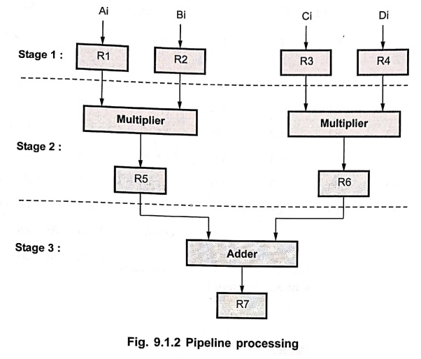
Fig.
9.1.2 shows the pipeline configuration to carry out the given task. It consists
of seven registers that receive new data with every clock pulse, two
multipliers and one adder circuit. The suboperations performed in each stage of
the pipeline are :
Stage 1:
R1 ← Ai, R2 ← Bi, R3 ← Ci, R4 ← Di
Stage 2 :
R5 ← R1 * R2, R6 ← R3 * R4
Stage 3 :
R7 ← R5 + R6
•
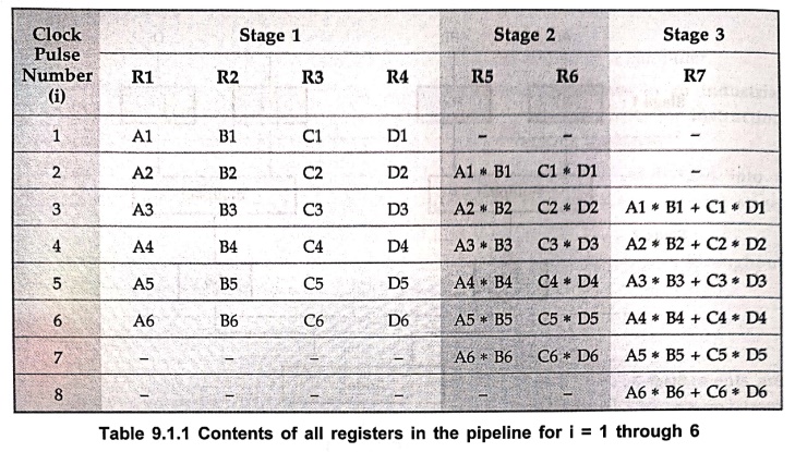
Table 9.1.1 shows contents of all registers in the pipeline for i = 1 through
6. The first clock pulse transfers A1, B1, C1 and D1 into R1, R2, R3 and R4,
respectively. The second clock pulse transfers the product of R1 and R2 into R5
and product of R3 and R4 into R6. The same clock pulse transfers A2, B2, C2 and
D2 into R1, R2, R3 and R4 respectively. The third clock pulse operates on all
three stages simultaneously. It places A3, B3, C3 and D3 into R1, R2, R3 and
R4, respectively, transfers the product of R1 and R2 into R5 and product of R3
and R4 into R6 and places sum of R5 and R6 into R7. It takes three clock pulses
to fill up the pipe and retrieve the first output from R7. From there on, each
clock produces a new output and moves the data one step down the pipeline. This
is continued as long as new input data flow into the system. When no more input
data are available, the clock must continue until the last output emerges out
of the pipeline.
2. Pipeline Model
1. Asynchronous Pipeline Model
•
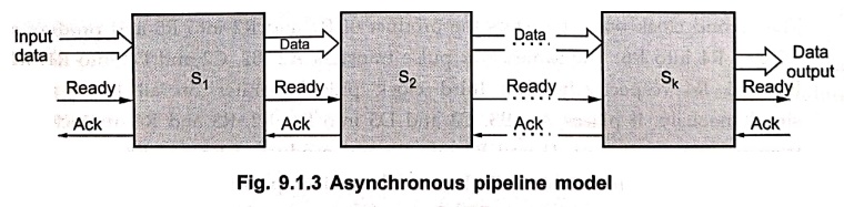
In asynchronous pipeline models, data flow along the pipeline stages is
controlled by a handshaking protocol, as shown in Fig. 9.1.3. When stage Si
is ready to transmit its result, it sends
a ready signal to stage Si+1. The result of Si is an
input data for stage Si+1, thus stage Si+ 1 accepts
result of Si as incoming data and returns an acknowledge signal to Si.
2. Synchronous Pipeline Model
•
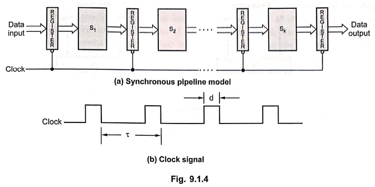
In synchronous pipeline model, clocked high speed registers are used to
interface between stages. At the falling edge of the clock pulse, all registers
transfer data to the next stages simultaneously. This is illustrated in Fig.
9.1.4.
Digital Principles and Computer Organization: Chapter 9: Pipelining : Tag: : - Pipelining: Stages and Model
Digital Principles and Computer Organization: Chapter 9: Pipelining
Under Subject

Digital Principles and Computer Organization
CS25C06 2nd Semester AIDS, CSE, IT, CSE(CY) Dept | 2025 Regulation | 2nd Semester 2025 Regulation
Related Subjects

English Essentials II
EN25C02 2nd Semester | 2025 Regulation | 2nd Semester 2025 Regulation

Tamils and Technology தமிழர்களும் தொழில்நுட்பமும்
UC25H02 2nd Semester | 2025 Regulation | 2nd Semester 2025 Regulation

Linear Algebra
MA25C02 2nd Semester | 2025 Regulation

Applied Physics (CSIE) II
PH25C03 2nd Semester AIDS, CSE, IT, CSE(CY) Dept | 2025 Regulation | 2nd Semester 2025 Regulation
Digital Principles and Computer Organization
CS25C06 2nd Semester AIDS, CSE, IT, CSE(CY) Dept | 2025 Regulation | 2nd Semester 2025 Regulation

Basic Electrical and Electronics Engineering
EE25C01 2nd Semester | 2025 Regulation | 2nd Semester 2025 Regulation

Python for Data Science
AD25201 2nd Semester AIDS Dept | 2025 Regulation | 2nd Semester 2025 Regulation

Re-Engineering for Innovation
ME25C05 2nd Semester | 2025 Regulation | 2nd Semester 2025 Regulation

Python for Data Science - Laboratory
AD25201 2nd Semester AIDS Dept | 2025 Regulation | 2nd Semester 2025 Regulation