Digital Principles and Computer Organization: Chapter 8: Instruction Set Architecture and Control Unit Design
Addressing Modes
Definition, Types
Questions: 1. What is the information conveyed by addressing modes ? 2. Define addressing mode. Classify addressing modes and explain each type with examples, 3. Differentiate direct and indirect addressing mode. 4. Distinguish between autoincrement and autodecrement addressing mode. 5. Define addressing mode and explain the basic addressing modes with an example for each. 6. What are addressing modes? Explain the various addressing modes with examples. 7. Define addressing mode in a computer. What are the different MIPS addressing modes? Give one example instruction to each category. 8. What do you mean by addressing modes? Explain the types of addressing modes that exists in modern processors ? 9. What is the need for addressing in a computer system? Explain the different addressing modes with suitable examples. 10. Elaborate the different types of addressing modes with a suitable example. 11. Explain direct, immediate, relative and indexed addressing modes with examples.
Addressing Modes
•
Part of the programming flexibility for each processor is the number and
different kind of ways the programmer can refer to data stored in the memory or
I/O device. The different ways that a processor can access data are referred to
as addressing schemes or addressing
modes.
•
An address computed by the processor when executing a memory access or branch
instruction or when fetching the next sequential instruction is known as Effective Address (EA). An effective
address can be made up from as many as three elements : The base, index and displacement.
•
An addressing mode specifies how to calculate the effective of an operand by
using elements of effective information held in registers and/or constants
contained within a machine instruction or elsewhere.
Types of addressing modes
Types of addressing
modes are :
1.
Register addressing mode.
2.
Absolute or direct addressing mode.
3.
Immediate addressing mode.
4.
Indirect addressing mode.
5.
Register indirect addressing mode.
6.
Displacement addressing mode.
7.
Relative addressing mode.
8.
Base register addressing.
9.
Index addressing mode.
10.
Auto–increment addressing mode.
11.
Auto–decrement addressing mode.
12.
Stack addressing mode.
1.
Register addressing mode : The operand is the contents of
processor register. The name of register is specified in the instruction.
•
Example : MOV R2, R1 : This
instruction copies the contents of register R2 to register R1.
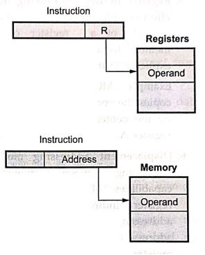
2.
Absolute or direct addressing mode : The address of the
location of the operand is given explicitly as a part of the instruction.
•
Example : MOV 2000, A : This instruction
copies the contents of memory location 2000 into the A register. As shown in the instruction, here,
address of operands is given explicitly in the instruction.
3.
Immediate addressing mode : The operand is given explicitly in
the instruction.
• Example : MOV
#20, A : This instruction copies operand 20 in the register A. The sign # in
front of the value of an operand is used to indicated that this value is an immediate operand.
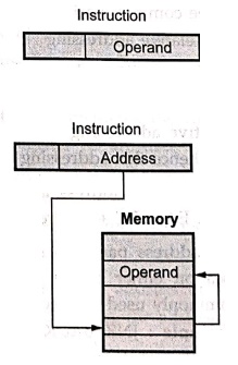
4.
Indirect addressing mode : In this addressing mode, the
instruction contains the address of memory which refers the address of the
operand.
5.
Register indirect addressing mode : The effective address
of the operand is the contents of a register or the main memory location whose
address is given explicitly in the instruction.
Example :
MOV (R0), A : This instruction copies the contents of memory addressed by the
contents of register R0 into the
register A.

6.
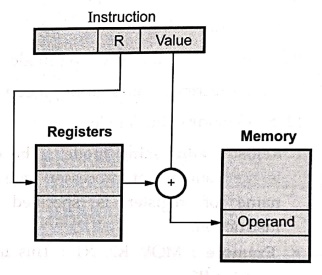
Displacement addressing mode : This addressing mode
combines the capabilities of direct addressing and register indirect
addressing. In this addressing mode, instruction has two address fields : Value and referenced register. The
effective address is computed by adding contents of referenced register to value.
EA
= value + (R)
Three
common variation of displacement addressing are :
■
Relative addressing
■
Base register addressing
■
Index addressing.
7.
Relative addressing mode : Here, the referenced register is
program counter (PC) and hence this addressing mode is also known as PC–relative addressing.
The
effective address is determined by adding the contents of PC to the address
field. EA = PC + Address part of instruction.
The
address part is a signed number so that it is possible to have branch target
location either before or after the branch instruction. This addressing mode is
commonly used to specify the target address in branch instructions.
• Example :
JNZ BACK: This instruction causes program execution to go to the branch target
location identified by the name BACK, if the branch condition is satisfied.
8. Base
register addressing : In this addressing mode, the referenced
register contains the main memory address and address field contains the
displacement. Displacement is usually unsigned integer number. EA = (R) +
Displacement.
• Example :
MOV [R+8], A : This instruction copies the contents of memory whose address is
determined by adding the contents of register R and displacement 8 to the
register A.
9. Index
addressing mode : In this addressing mode, the address
field references the main memory and the referenced register contains a
positive displacement from that address. EA = Memory address + (R).
The
indexing is a technique that allows programmer to point or refer the data
(operand) stored in sequential memory locations one by one. It is an efficient
mechanism for performing iterative operations.
• Example :
MOV [R1 + RI], R : In this instruction main memory address is given by register
R1 and the referenced register RI gives the positive displacement. The contents
of the memory address generated by the addition of main memory address and
displacement is copied to register R.
10.
Autoincrement addressing mode : The effective address
of the operand is the contents of a register specified in the instruction.
After accessing the operand, the contents of this register are incremented to
address the next location.
• Example :
MOV R0, (R2)+ : The above instruction copies the contents of register R0 into
the memory location whose address is specified by the contents of register R2.
After copy operation, the contents of register R2 are automatically incremented
at by 1.
11. Autodecrement
addressing mode : The contents of a register specified in
the instruction are decremented and then they are used as an effective address
to access a memory location.
• Example :
MOV – (R0), R1 : This instruction, initially decrements the contents of
register R0 and then the decremented contents of register R0 are used to
address the location. Finally, the contents from the addressed memory location
are memory copied into the register R1.
12. Stack
addressing mode : A stack is linear array of reserved
memory locations. It is associated with a pointer called Stack Pointer (SP).
In
stack addressing mode, stack pointer always contains the address of Top Of
Stack (TOS) where the operand is to be stored or located. Thus, the address of
the operand (source or destination) is the contents of stack pointer.
This
addressing mode is the special case of register indirect addressing where
referenced register is a stack pointer.
Usually,
stack grows in the direction of descending addresses, (descending stack),
starting from a high address and progressing to lower one. In this stack, SP is
decremented before any items are appended (pushed) on stack and SP is
incremented after any items popped from the stack.
• Example :
PUSH R : This instruction decrements SP and copies the contents of register R
on to the top of stack pointed by stack pointer.
MIPS addressing modes
The
MIPS addressing modes are as follows :
1. Immediate addressing
:
In this addressing mode, the operand is a constant within the instruction
itself.

Example :
lui $s0, 61 // Loads decimal 61 in upper 16 bits register $s0
2. Register addressing :
In
this addressing mode, the operand is a register
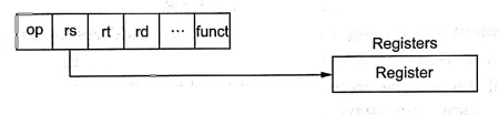
Example :
add $t1,$s0, $s1 // Adds contents of $s0 and $s1 and store result in St1.
3. Base or displacement
addressing : In this addressing mode, the operand is
at the memory location whose address is the sum of a register and a constant in
the instruction.
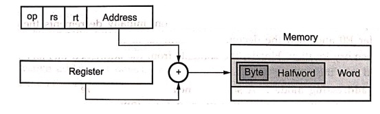
Example : lw $t1, 4 ($t2)
// where $t1 = rs, $t2 = base (memory
address),
4 = offset value
Thus
; $t1 = Memory [$t2 +4]
4. PC–relative
addressing : In this addressing mode, the branch
address is the sum of the PC and a constant in the instruction.
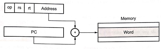
Example :
beq $0,$3,Label
5. Pseudodirect
addressing : In this addressing mode, the jump
address is the 26 bits of the instruction concatenated with the upper bits of
the PC. Address in Pseudo–Direct must be a multiple of four.
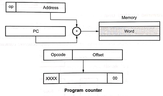
Example :
j label // go to location label.
Review Questions
1. What is the
information conveyed by addressing modes ?
2. Define addressing
mode. Classify addressing modes and explain each type with examples,
3. Differentiate direct
and indirect addressing mode.
4. Distinguish between
autoincrement and autodecrement addressing mode.
5. Define addressing
mode and explain the basic addressing modes with an example for each.
6. What are addressing
modes? Explain the various addressing modes with examples.
7. Define addressing
mode in a computer. What are the different MIPS addressing modes? Give one
example instruction to each category.
8. What do you mean by
addressing modes? Explain the types of addressing modes that exists in modern
processors ?
9. What is the need
for addressing in a computer system? Explain the different addressing modes
with suitable examples.
10. Elaborate the
different types of addressing modes with a suitable example.
11. Explain direct,
immediate, relative and indexed addressing modes with examples.
Digital Principles and Computer Organization: Chapter 8: Instruction Set Architecture and Control Unit Design : Tag: : Definition, Types - Addressing Modes
Digital Principles and Computer Organization: Chapter 8: Instruction Set Architecture and Control Unit Design
Under Subject

Digital Principles and Computer Organization
CS25C06 2nd Semester AIDS, CSE, IT, CSE(CY) Dept | 2025 Regulation | 2nd Semester 2025 Regulation
Related Subjects

English Essentials II
EN25C02 2nd Semester | 2025 Regulation | 2nd Semester 2025 Regulation

Tamils and Technology தமிழர்களும் தொழில்நுட்பமும்
UC25H02 2nd Semester | 2025 Regulation | 2nd Semester 2025 Regulation

Linear Algebra
MA25C02 2nd Semester | 2025 Regulation

Applied Physics (CSIE) II
PH25C03 2nd Semester AIDS, CSE, IT, CSE(CY) Dept | 2025 Regulation | 2nd Semester 2025 Regulation
Digital Principles and Computer Organization
CS25C06 2nd Semester AIDS, CSE, IT, CSE(CY) Dept | 2025 Regulation | 2nd Semester 2025 Regulation

Basic Electrical and Electronics Engineering
EE25C01 2nd Semester | 2025 Regulation | 2nd Semester 2025 Regulation

Python for Data Science
AD25201 2nd Semester AIDS Dept | 2025 Regulation | 2nd Semester 2025 Regulation

Re-Engineering for Innovation
ME25C05 2nd Semester | 2025 Regulation | 2nd Semester 2025 Regulation

Python for Data Science - Laboratory
AD25201 2nd Semester AIDS Dept | 2025 Regulation | 2nd Semester 2025 Regulation