Digital Principles and Computer Organization: Chapter 8: Instruction Set Architecture and Control Unit Design
Hardwired Control Unit
Questions: 1. Draw and explain typical hardwired control unit. 2. With a diagram which shows the separation decoding and encoding functions, explain hardwired control. 3. Show the generation Zin and end control signal.
Hardwired Control Unit
In
the hardwired control, the control units use fixed logic circuits to interpret
instructions and generate control signals from them.
•
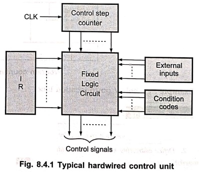
The fixed logic circuits use contents of the control step counter, contents of
the instruction register, contents of the condition code flag and the external
input signals such as MFC and interrupt requests to generate control signals.
•
Fig. 8.4.1 shows the typical hardwired control unit. Here, the fixed logic
circuit block includes combinational circuit(decoder and encoder) that generates
the required control outputs, depending on the state of all its inputs.
•
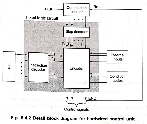
By separating the decoding and encoding functions, we can draw more detail
block diagram for hardwired control unit as shown in Fig. 8.4.2.
•
The instruction decoder decodes the instruction loaded in the IR. If IR is an 8–bit
register then instruction decoder generates 28, i.e. 256 lines; one
for each instruction. According to code in the IR, only one line amongst all
output lines of decoder goes high i.e., set to 1 and all other lines are set to
0.
•
The step decoder provides a separate signal line for each step, or time slot,
in a control sequence. The encoder gets in the input from instruction decoder,
step decoder, external inputs and condition codes. It uses all these inputs to
generate the individual control signals.
•
After execution of each instruction end signal is generated which resets
control step counter and make it ready for generation of control step for next
instruction.
•
Let us see how the encoder generates signal for single bus processor
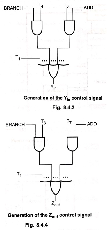
organisation shown in Fig. 8.4.3 Yin. The encoder circuit implements
the following logic function to generate Yin.
Yin
꞊ T1 + T6 . ADD +
T4 . BRANCH + ..
•
The Yin signal is asserted during time interval T1 for
all instructions, during T6 for an ADD instruction, during T4
for an unconditional BRANCH instruction and so on.
•
As another example, the logic function to generate Zout signal can
given by,
Zout
꞊ T2 + T7 . ADD + T6 . BRANCH + …
Generation of the Yin control signal
Generation of the Zout
control signal
•
The Zout signal is asserted during time interval T2 of
all instructions, during T7 for an ADD instruction, during T6
for an unconditional branch instruction and so on.
•
Fig. 8.4.3 and 8.4.4 shows the hardware implementation of logic functions for Yin
and Zout control signals.
Example: 1
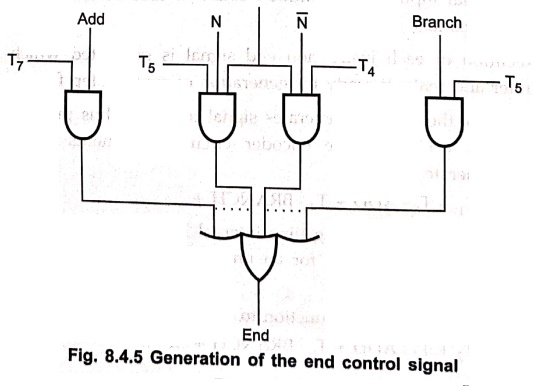
Generate the logic
circuit for the following function
End = T7 .
ADD + T5 . BR + (T5 . N+T4 .  ) . BRN
+........
) . BRN
+........
Solution :
Fig.
8.4.5 shows the circuit that generates the End control signal from the logic
function.
End
= T7 . ADD + T5 . BR + (T5 . N+T4 . ) . BRN +......
Advantages of hardwired control unit
•
Hardwired control unit is fast because control signals are generated by combinational
circuits.
•
The delay in generation of control signals depends upon the number of gates.
•It
has greater chip area efficiency since its uses less area on–chip.
Disadvantages of hardwired control unit
•
More the control signals required by CPU; more complex will be the design of control
unit.
•
Modifications in control signal are very difficult. That means it requires
rearranging of wires in the hardware circuit.
•
It is difficult to correct mistake in original design or adding new feature in
existing design of control unit.
Review Questions
1. Draw and explain
typical hardwired control unit.
2. With a diagram
which shows the separation decoding and encoding functions, explain hardwired
control.
3. Show the generation
Zin and end control signal.
Digital Principles and Computer Organization: Chapter 8: Instruction Set Architecture and Control Unit Design : Tag: : - Hardwired Control Unit
Digital Principles and Computer Organization: Chapter 8: Instruction Set Architecture and Control Unit Design
Under Subject

Digital Principles and Computer Organization
CS25C06 2nd Semester AIDS, CSE, IT, CSE(CY) Dept | 2025 Regulation | 2nd Semester 2025 Regulation
Related Subjects

English Essentials II
EN25C02 2nd Semester | 2025 Regulation | 2nd Semester 2025 Regulation

Tamils and Technology தமிழர்களும் தொழில்நுட்பமும்
UC25H02 2nd Semester | 2025 Regulation | 2nd Semester 2025 Regulation

Linear Algebra
MA25C02 2nd Semester | 2025 Regulation

Applied Physics (CSIE) II
PH25C03 2nd Semester AIDS, CSE, IT, CSE(CY) Dept | 2025 Regulation | 2nd Semester 2025 Regulation
Digital Principles and Computer Organization
CS25C06 2nd Semester AIDS, CSE, IT, CSE(CY) Dept | 2025 Regulation | 2nd Semester 2025 Regulation

Basic Electrical and Electronics Engineering
EE25C01 2nd Semester | 2025 Regulation | 2nd Semester 2025 Regulation

Python for Data Science
AD25201 2nd Semester AIDS Dept | 2025 Regulation | 2nd Semester 2025 Regulation

Re-Engineering for Innovation
ME25C05 2nd Semester | 2025 Regulation | 2nd Semester 2025 Regulation

Python for Data Science - Laboratory
AD25201 2nd Semester AIDS Dept | 2025 Regulation | 2nd Semester 2025 Regulation