Digital Principles and Computer Organization: Chapter 6: Sequential Circuits - Counters
Design of Synchronous Counters
Questions: 1. Explain the design steps of Mod n counter. 2. Design synchronous MOD-6 counter. 3. Design a 4 bit binary counter and explain its counting process. Discuss how to use this circuit to perform both up and down counting.
Design of Synchronous
Counters
1.
Determine the number of flip–flops needed. If n represents number of flip–flops
2n ≥ number of states in the counter.
2.
Choose the type of flip–flops to be used.
3.
Using excitation table for selected flip–flop determine the excitation table
for the counter.
4.
Use K–map or any other simplification method to derive the flip–flop input
functions.
5.
Draw the logic diagram.
Example: 1
Design a MOD–5
synchronous counter using JK flip–flops and implement it.
Step 1 : Determine
the number of flip–flop needed Flip–flops required are
2n ≥ N
Here N = 5
n
= 3 i.e. three flip–flops are required.
Step 2 : Type
of flip–flop to be used : JK
Step 3 : Determine
the excitation table for the counter.
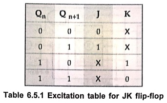
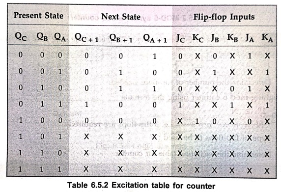
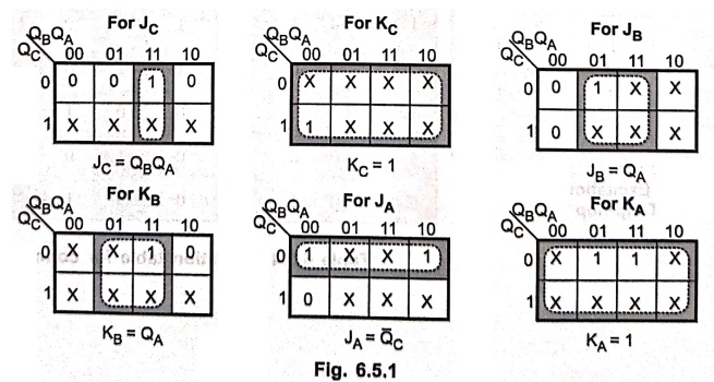
Step 4 : K–Map
simplification
Step 5 : Draw
the logic daigram
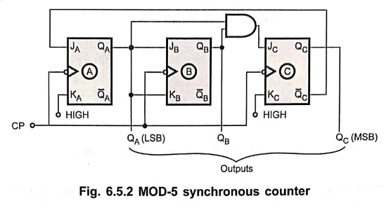
Example: 2
Design divide by 6
counter using T–flip–flops. Write state table and reduce the expression using K–map.
Solution :
Step 1 :
Determine the number of flip–flops needed.
For
designing mod 6 counter using the formula
2n ≥ N
Here N = 6
n n = 3 i.e. 3 flip–flops
are required.
Step 2 :
Type of flip–flops to be used : T
Step 3 :
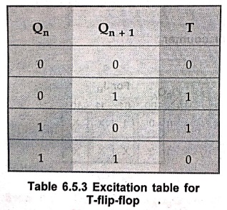
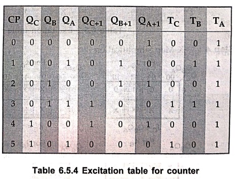
Determine the excitation table for counter.
Step 4 :
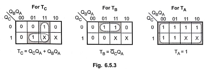
K–map simplification.
Step 5 :
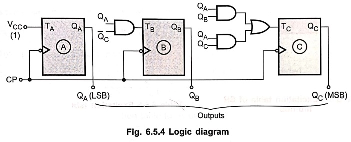
Draw the logic diagram.
Example: 3
Using positive edge
triggering SR flip–flops design a counter which counts in the following
sequence:
000, 111, 110, 101,
100, 011, 010, 001, 000,
Solution :
Step 1:
Determine the number of flip–flops needed
We
know that 2n ≥ N. Here, N
= 8 n = 3
Step 2 : Type
of flip–flop to be used: SR
Step 3 :
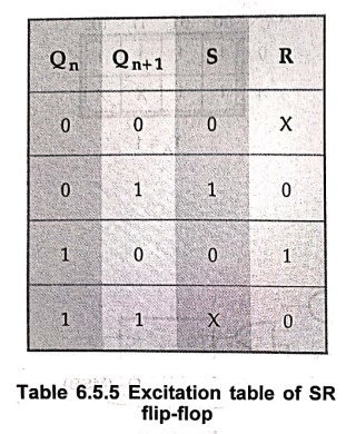
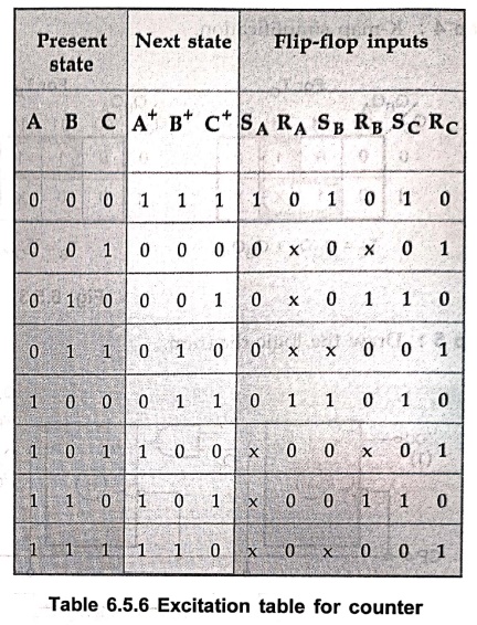
Determine the excitation table for counter.
Here,
the next state for each present state is written according to given sequence.
For example, the next state for the present state 000 is 111.
Step 4 : K–map
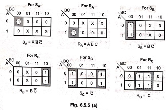
simplification.
Step 5 : Draw
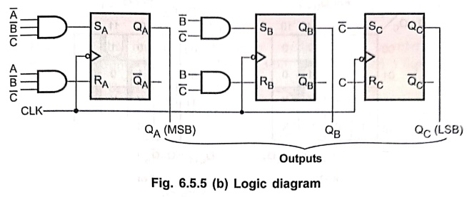
logic diagram
Example: 4
Design a synchronous
decade counter using D flip–flop.
Solution :
The
decade counter is a mod–10 counter. It has ten states : 0 – 9.
Step 1 :
Determine the number of flip–flops needed.
We
know that 2n ≥ N. Here, N
10
n
= 4 i.e. 4 flip–flops needed.
Step 2 : Types
of flip–flops to be used : D
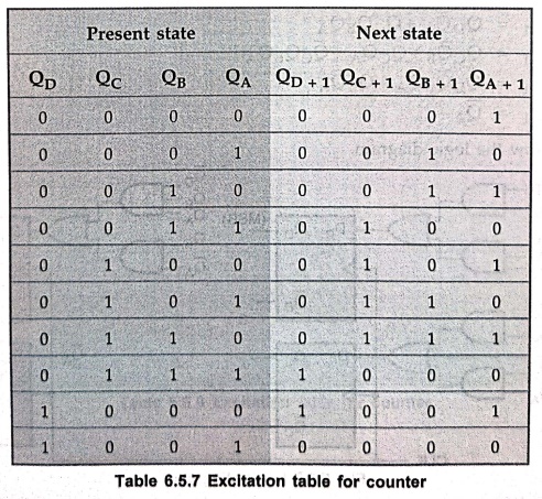
Step 3 : Determine
the excitation table for counter.
Step 4 :
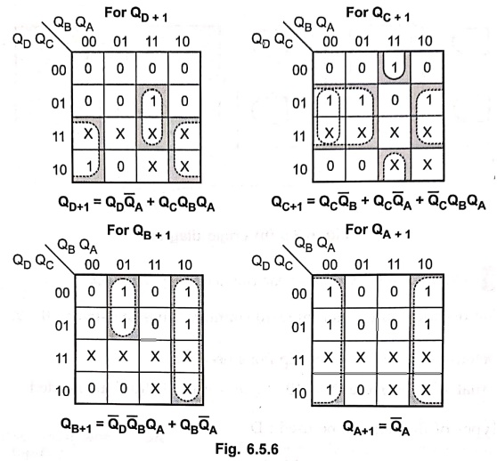
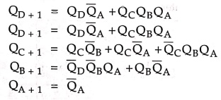
K–map simplification
Step 5 :
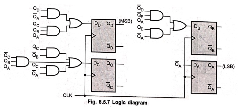
Draw the logic diagram.
Example: 5
Design a counter to
count the sequence 0, 1, 2, 4, 5, 6 using SR FFs.
Solution :
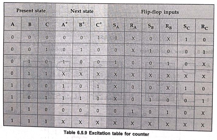
Step 1 : Determine
the number of flip–flops needed. Here, counter should count maximum count = 6 =
(110)2 which is 3–bit. Thus, we need 3 flip–flops.
Step 2 : Flip–flops
to be used: SR.
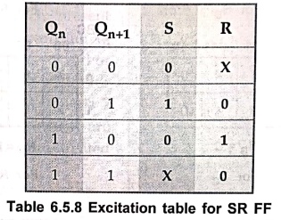
Step 3 : Excitation
table for the counter can be obtained according to the excitation table of SR
FF.
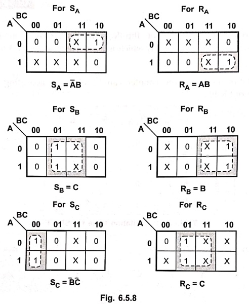
Step 4 :
K–map simplification.
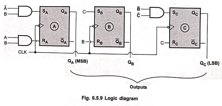
Step 5 : Draw
logic diagram
Example: 6
Design a counter with
the sequence 0, 1, 3, 7, 6, 4, 0.
Solution :
Step 1 : Determine
the number of flip–flops needed. Here, counter should count maximum count = 7 =
(111)2 which is 3–bit. Thus, we need 3–flip–flops.
Step 2 :
Flip–flops to be used: JK.
Step 3 : Determine
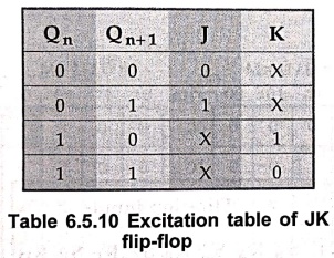
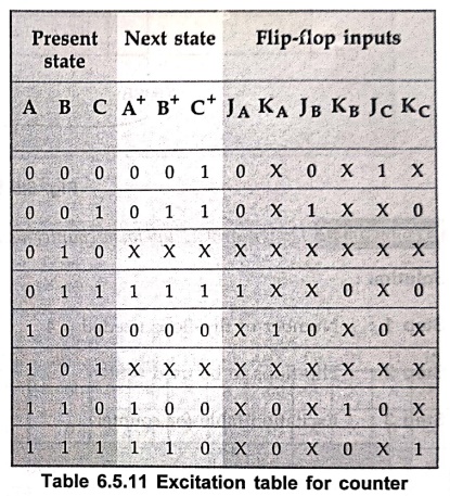
the excitation table for counter. Here, the next state for each present state
is written according to given sequence. For example, the next state for the
present state 3 (011) is 7 (111). The counts which are not in sequence are
treated as don't cares.
Step 4 :
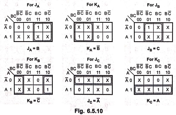
K–map simplification
Step 5 :
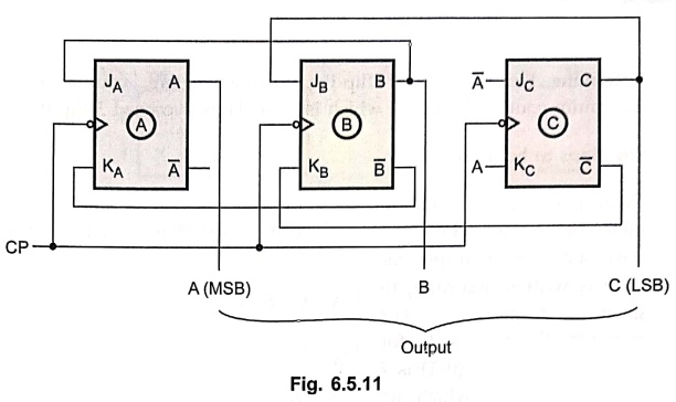
Draw logic diagram.
Example: 7
Design a BCD up / down
counter using SR flip–flops.
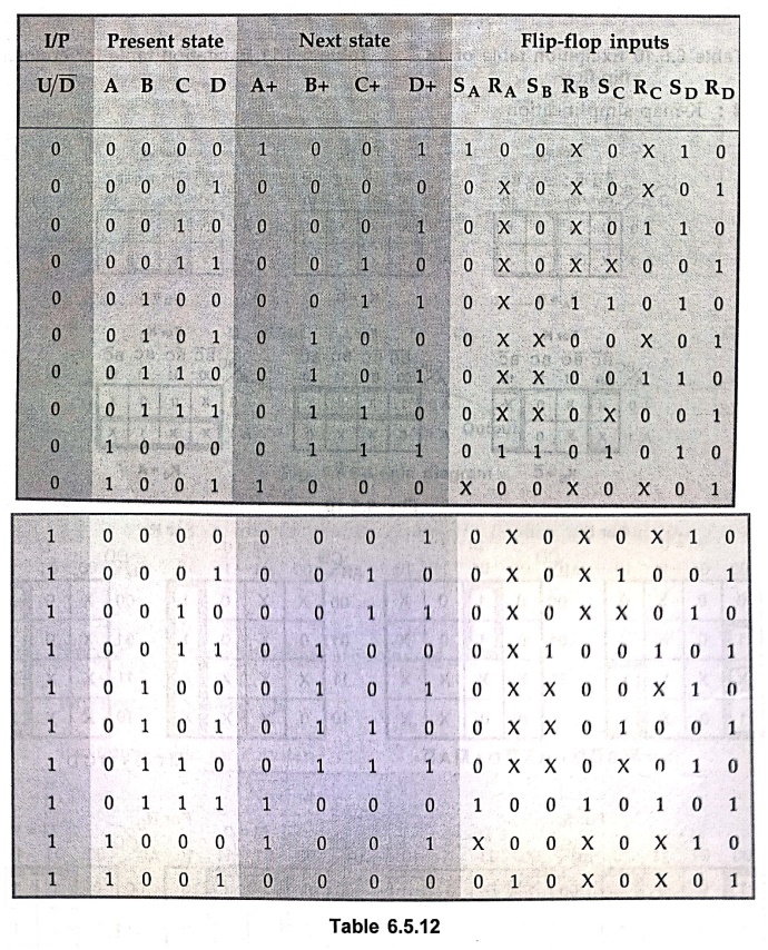
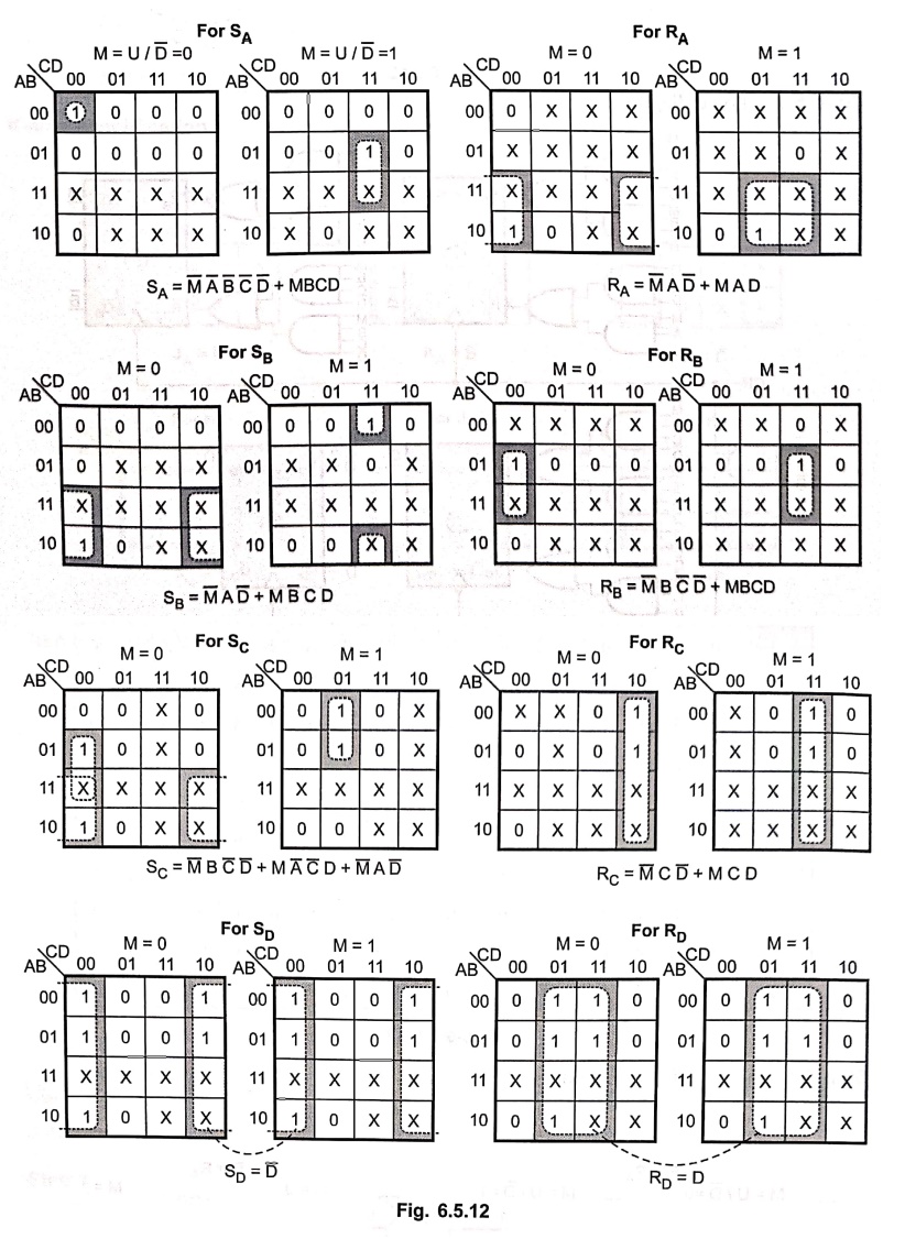
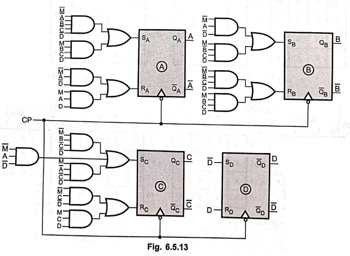
Solution :
Step 1 : Number
of flip–flops needed = 4
Step 2 : Flip–flops
to be used = SR
Step 3 : Excitation
table for counter
Step 4 : K–map
simplification
Step 5 : Logic
diagram
Example: 8
Design a synchronous
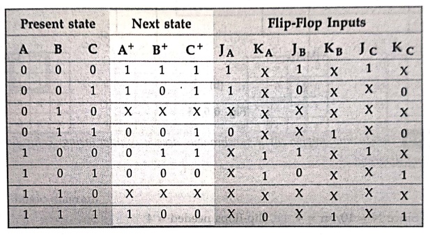
counter using JK flip–flop to count the following sequence 7, 4, 3, 1, 6, 0, 7
......
Solution :
Step 1: Since
23 > 7, three flip–flops are required
Step 2 : Flip–flops
to be used : JK
Step 3 : Excitation
table for counter
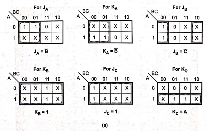
K–map simplification
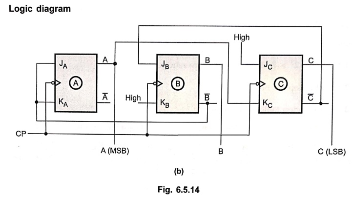
Logic diagram
Example: 9
Design and implement a
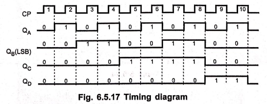
synchronous decade counter using T flip–flop. Draw the timing diagram.
Solution :
Step 1: Since
N = 10, n = 4 i.e. flip–flops needed = 4
Step 2 : Flip–flops
to be used: T
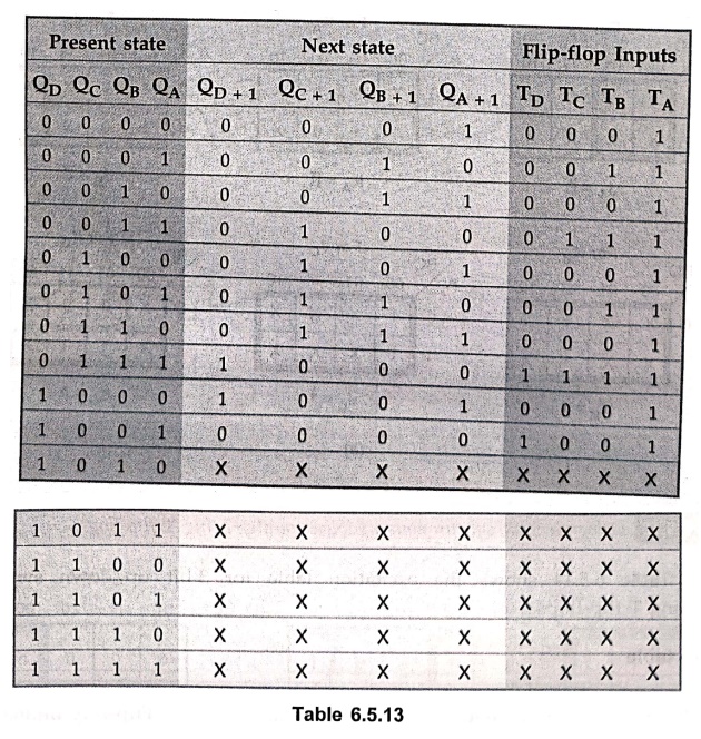
Step 3 : Determine
excitation table for counter
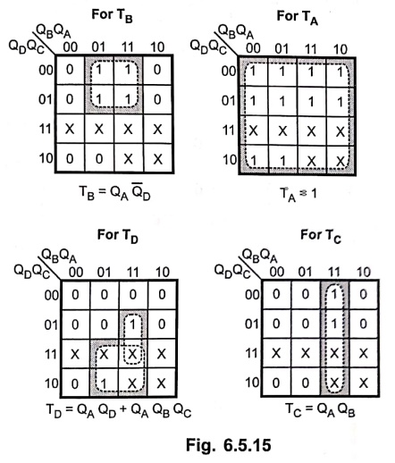
Step 4 : K–map
simplification
Step 5 :
Logic diagram
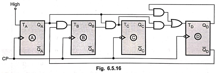
Step 6 : Timing diagram
Fig.
6.5.17 shows the timing diagram for the synchronous decade counter.
Example: 10
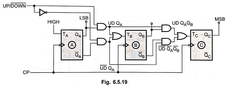
Design a 3–bit
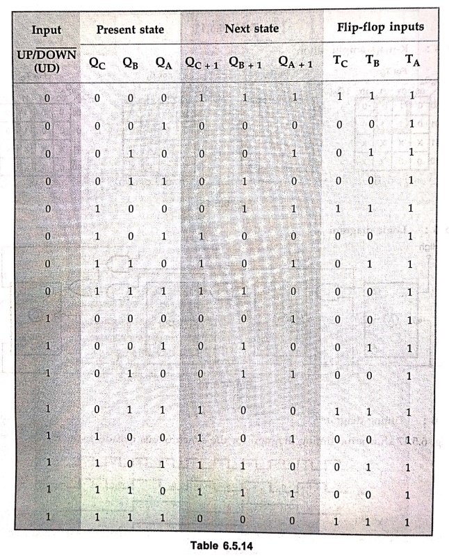
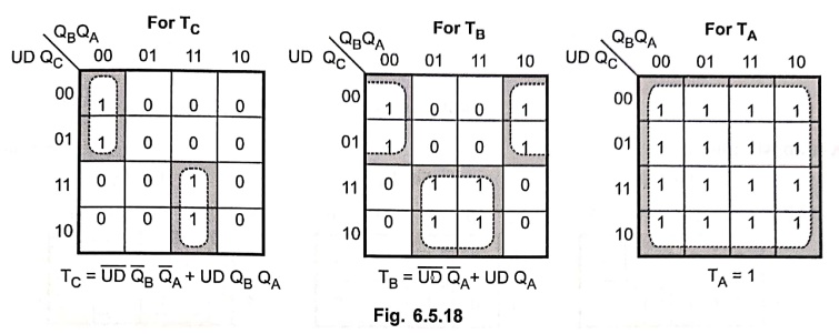
synchronous updown counter using T flip–flops.
Solution :
Table
6.5.14 shows the excitation table for 3–bit up/down synchronous counter using T
flip–flops.
Excitation table
K–map simplification
Logic diagram
Example: 11
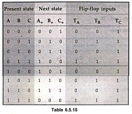
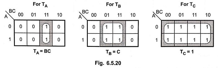
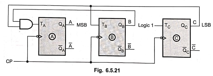
Design a three bit
binary counter using T flip–flops
Solution :
Table
6.5.15 shows the excitation table for 3–bit binary counter.
K–map simplification
Logic diagram
Example: 12
Design and explain the
working of a synchronous mod–3 counter.
Solution :
Step 1 :
N = 3 and since 22 > 3, n = 2 i.e. Flip–Flops needed = 2.
Step
2 : Flip–Flops
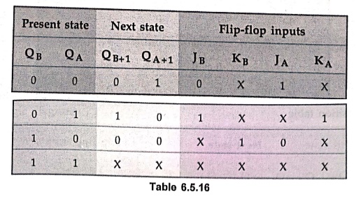
used : JK
Step 3 : Transition
table
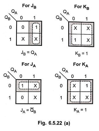
Step 4 :
K–map simplification
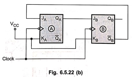
Step 5 : Logic
diagram
Example: 13
Design and explain the
working of mod–7 counter.
Solution :
Step 1:
N = 7, and since 23 > 7, n = 3 i.e. Flip–Flops needed = 3
Step 2 :
Flip–Flops used : JK
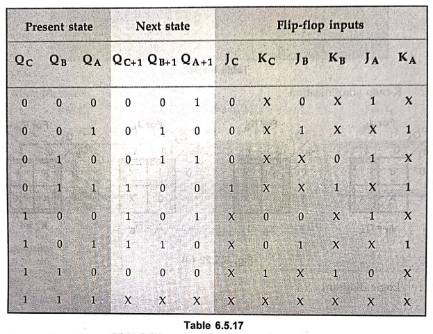
Step 3 :
Transition table
Step 4 :
K–map simplification
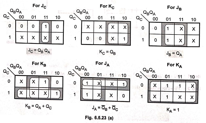
Step 5 :
Logic diagram
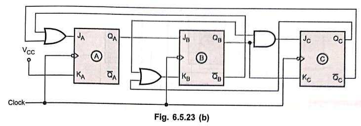
Example: 14
Design a synchronous
counter with states 0, 1, 2, 3, 0, 1..... using JK FFs.
Solution :
Step 1: Here,
N = 4 and since 22 ≥ 4 we need 2 Flip–Flops
Step 2 :
Flip–Flops to be used : JK
Step 3 :
Transition table
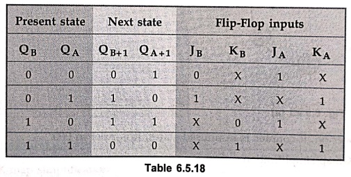
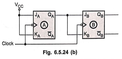
Step 4 :
K–map simplification
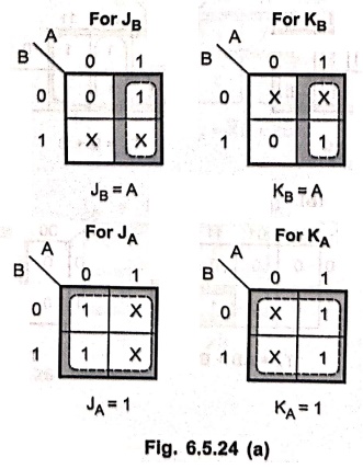
Step 5 : Logic
diagram
Example: 15
Design a 3–bit binary
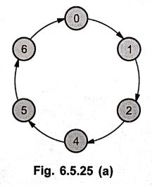
counter using T flip–flop that has a repeated sequence of six states. 000–001–010–100–101–110.
Give the state table, state diagram and logic diagram. Next states for unused
states should be 000.
Solution :
Step 1:
State diagram
Step 2 :
State table
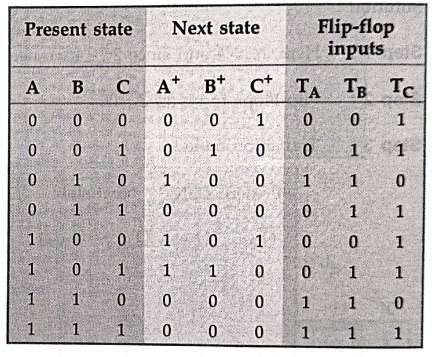
Upon
power on, if counter is in unused states, it is reset to 000.
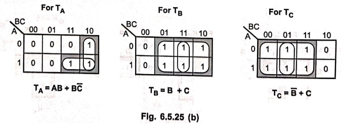
Step 3 :
K–map simplification
Step 4 : Logic
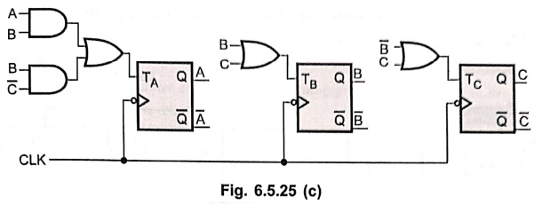
diagram
Example: 16
Design a synchronous
up/down counter that will count up from zero to one to two to three and will
repeat whenever an external input x is logic 0, and will count down from three
to two to one to zero and will repeat whenever the external input x is logic 1.
Implement your circuit with one TTL SN74LS76 device and one TTL SN74LS00
device.
Solution :
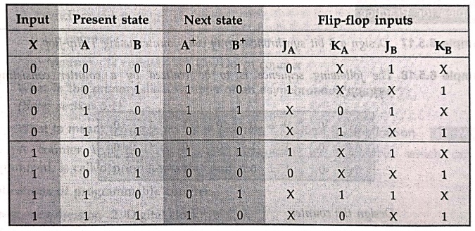
Step 1 :
Excitation table
Step 2 :
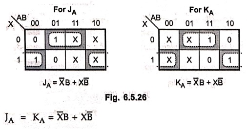
K–map simplification
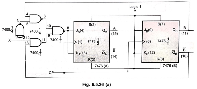
Step 3 : Logic
diagram
We
can implement combinational logic circuit for JA and KA
input using NAND–NAND logic, as shown in Fig. 6.5.26.
Examples for Practice
Example: 17
Design a 3 bit
synchronous gray code counter using T flip–flop.
Example: 18
The following sequence
is to be realized by a counter consisting of 3 JK FF's.
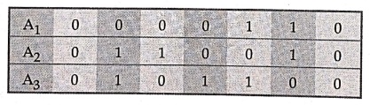
Design
the counter.
Example: 19
Design and explain the
working of a mod–11 counter.
Example: 20
Design and draw the
output waveform of UP/DOWN counter using JK–FF.
Example: 21
Design and explain the
working of a synchronous mod–3 counter.
Example: 22
Using SR flipflops
design a parallel counter which counts in the sequence 000, 111, 101, 110, 001,
010, 000, ...
Review Questions
1. Explain the design
steps of Mod n counter.
2. Design synchronous
MOD–6 counter.
3. Design a 4 bit
binary counter and explain its counting process. Discuss how to use this
circuit to perform both up and down counting.
Digital Principles and Computer Organization: Chapter 6: Sequential Circuits - Counters : Tag: : - Design of Synchronous Counters
Digital Principles and Computer Organization: Chapter 6: Sequential Circuits - Counters
Under Subject

Digital Principles and Computer Organization
CS25C06 2nd Semester AIDS, CSE, IT, CSE(CY) Dept | 2025 Regulation | 2nd Semester 2025 Regulation
Related Subjects

English Essentials II
EN25C02 2nd Semester | 2025 Regulation | 2nd Semester 2025 Regulation

Tamils and Technology தமிழர்களும் தொழில்நுட்பமும்
UC25H02 2nd Semester | 2025 Regulation | 2nd Semester 2025 Regulation

Linear Algebra
MA25C02 2nd Semester | 2025 Regulation

Applied Physics (CSIE) II
PH25C03 2nd Semester AIDS, CSE, IT, CSE(CY) Dept | 2025 Regulation | 2nd Semester 2025 Regulation
Digital Principles and Computer Organization
CS25C06 2nd Semester AIDS, CSE, IT, CSE(CY) Dept | 2025 Regulation | 2nd Semester 2025 Regulation

Basic Electrical and Electronics Engineering
EE25C01 2nd Semester | 2025 Regulation | 2nd Semester 2025 Regulation

Python for Data Science
AD25201 2nd Semester AIDS Dept | 2025 Regulation | 2nd Semester 2025 Regulation

Re-Engineering for Innovation
ME25C05 2nd Semester | 2025 Regulation | 2nd Semester 2025 Regulation

Python for Data Science - Laboratory
AD25201 2nd Semester AIDS Dept | 2025 Regulation | 2nd Semester 2025 Regulation