Digital Principles and Computer Organization: Chapter 6: Sequential Circuits - Counters
Design of Ripple (Asynchronous) Counters
Review Questions: 1. Explain the working of BCD ripple counter with timing diagrams. 2. Design mod 5 ripple counter using T Flip-Flops.
Design of Ripple
(Asynchronous) Counters
The
steps involved in the design of asynchronous counter are :
1.
Determine the number of flip–flops needed.
2.
Choose the type of flip–flops to be used : T or JK. If T flip–flops are used
connect T input of all flip–flops to logic 1. If JK flip–flops are used connect
both J and K inputs of all flip flops to logic 1.
Such
connection toggles the flip–flop output on each clock transition.
3.
Write the truth table for the counter.
4.
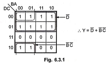
Derive the reset logic by K–map simplification.
5.
Draw the logic diagram.
Example: 1
Design BCD ripple
counter using JK flip–flop.
Solution :
Step 1: Determine
the number of flip–flops needed. The BCD counter goes through states 0–9, i.e.
total 10 states. Thus, N = 10 and for 2n ≥ N, we need n = 4, i.e. 4 flip–flops required.
Step 2 : Type
of flip–flops to be used: JK
Step 3 : Write
the truth table for the counter
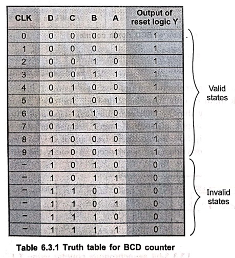
Note :
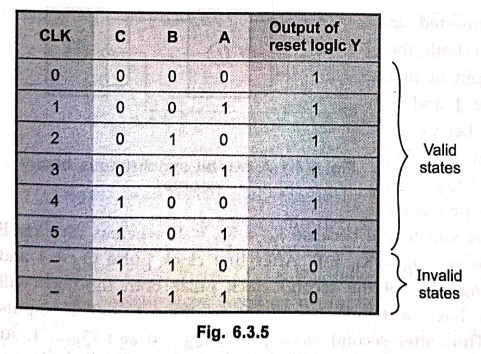
The reset input (CLR) of each Flip–Flop is active–low input. By making CLR
input of all Flip–Flops logic 0, we can reset the counter. Thus reset logic is designed
such a way that for invalid states, Y = 0 and counter resets.
Step 4 :
Derive reset logic
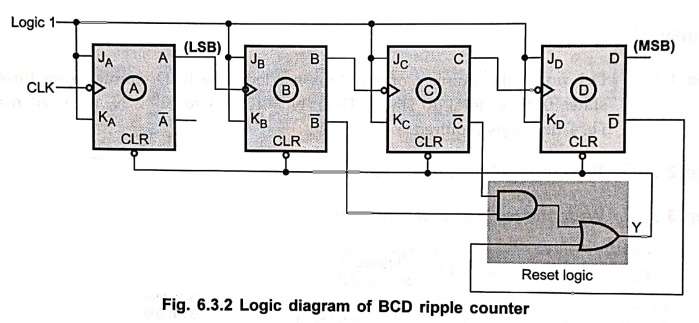
Step 5 : Draw
logic diagram.
Example: 2
Design a 3–bit
asynchronous ripple counter using T flip–flops and explain its operation.
Solution :
Fig. 6.3.3 shows a 3–bit asynchronous ripple counter using T flip–flops. As
shown in Fig. 6.3.3, the clock input of only first stage flip–flop. The clock
input of the second stage flip–flop is triggered by the QA output of
the first stage and third stage flip–flop is triggered by the QA
output of second stage. Because of the inherent propagation delay time through
a flip–flop, a transition of the input clock pulse and a transition of the QA
output of previous stage can never occur at exactly the same time.
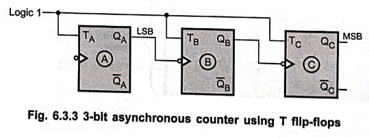
Therefore,
flip–flops are never simultaneously triggered, which results in asynchronous counter
operation.
Since,
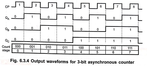
T input is connected to logic 1 each flip–flop toggles at clock input. Fig.
6.3.4 shows the timing diagram for 3–bit asynchronous counter.
Example: 3
Design mod 6 ripple
counter using T flip–flops.
Solution :
Step 1 : Determine
the number of flip–flop required. Here, counter goes through 0 – 5 states,
i.e., total 6 states. Thus N = 6 and for 2n ≥ N we need n
= 3, i.e. 3 flip–flops.
Step 2 :
Type of flip–flops to be used : T
Step 3 :
Write the truth table for counter
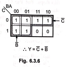
Step 4 : Derive
reset logic
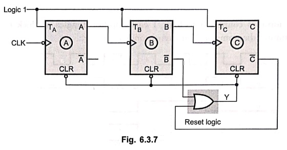
Step 5 : Draw
logic diagram
Review Questions
1. Explain the working
of BCD ripple counter with timing diagrams.
2. Design mod 5 ripple
counter using T Flip–Flops.
Digital Principles and Computer Organization: Chapter 6: Sequential Circuits - Counters : Tag: : - Design of Ripple (Asynchronous) Counters
Digital Principles and Computer Organization: Chapter 6: Sequential Circuits - Counters
Under Subject

Digital Principles and Computer Organization
CS25C06 2nd Semester AIDS, CSE, IT, CSE(CY) Dept | 2025 Regulation | 2nd Semester 2025 Regulation
Related Subjects

English Essentials II
EN25C02 2nd Semester | 2025 Regulation | 2nd Semester 2025 Regulation

Tamils and Technology தமிழர்களும் தொழில்நுட்பமும்
UC25H02 2nd Semester | 2025 Regulation | 2nd Semester 2025 Regulation

Linear Algebra
MA25C02 2nd Semester | 2025 Regulation

Applied Physics (CSIE) II
PH25C03 2nd Semester AIDS, CSE, IT, CSE(CY) Dept | 2025 Regulation | 2nd Semester 2025 Regulation
Digital Principles and Computer Organization
CS25C06 2nd Semester AIDS, CSE, IT, CSE(CY) Dept | 2025 Regulation | 2nd Semester 2025 Regulation

Basic Electrical and Electronics Engineering
EE25C01 2nd Semester | 2025 Regulation | 2nd Semester 2025 Regulation

Python for Data Science
AD25201 2nd Semester AIDS Dept | 2025 Regulation | 2nd Semester 2025 Regulation

Re-Engineering for Innovation
ME25C05 2nd Semester | 2025 Regulation | 2nd Semester 2025 Regulation

Python for Data Science - Laboratory
AD25201 2nd Semester AIDS Dept | 2025 Regulation | 2nd Semester 2025 Regulation