Applied Physics I: Chapter 5: Oscillations and Waves - Ultrasonics
Piezo-Electric Effect and Piezo-Electric Method
Principle, Construction, Working, Condition, Limitations - Production of Ultrasonics
The crystals which produces piezo‒electric effect and converse piezo‒electric effect are termed as piezo‒electric crystals.
PIEZO‒ELECTRIC
EFFECT AND PIEZO‒ELECTRIC METHOD
Piezo‒Electric Crystals
The
crystals which produces piezo‒electric effect and converse piezo‒electric
effect are termed as piezo‒electric crystals.
Examples:
Quartz, Tourmaline, Rochelle salts etc.
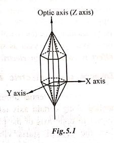
A
typical example for a piezo‒electric crystal (Quartz), is as shown in Fig.5.1.
It has an hexagonal shape with pyramids attached at both ends. It consists of 3
axes, viz., (i) optic axis (Z‒ axis), which joins the edges of the pyramid,
(ii) Electrical axis (X‒axis), which joins the corners of the hexagon and (iii)
mechanical axis (Y‒axis), which joins the centre (or) sides of the hexagon, as
shown in Fig.5.1.
NOTE:
All the 3 axes are mutually perpendicular to each other.
X‒cut and Y‒cut crystals
X‒cut crystal:
When the crystal is cut perpendicular to the X‒axis, as shown in Fig.5.2, then
it is called X‒cut crystal.

Generally
X‒cut crystals are used to produce longitudinal ultrasonic waves.
Y‒cut crystals:
When the crystal is cut perpendicular to the Y axis, as shown in Fig.5.3, then
it is called Y‒cut crystal.
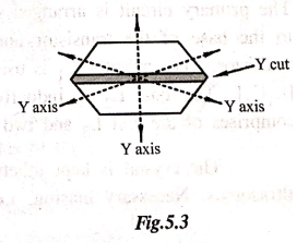
Generally
Y‒cut crystals produces transverse ultrasonic waves.
Piezo electric effect
When
pressure (or) mechanical force is applied along certain axis (mechanical axis)
with respect to optic axis of the crystals like quartz, tourmaline, rochelle
salts etc., then equal and opposite charges are produced along the
perpendicular axis (electrical axis) with respect to optic axis of the crystal
as shown in Fig 5.4. This effect is called
piezo electric effect.

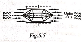
Inverse piezo electric effect
When
potential difference (or) e.m.f. is applied along certain axis (electrical
axis) with respect to optic axis of the piezoelectric crystals then the crystal
starts vibrating along the perpendicular axis (Mechanical axis) with respect to
the crystal as shown in Fig 5.5. This effect is called as inverse piezo electric effect.
Principle
Inverse
piezo electric effect is the principle behind the production of ultrasonics
using piezo electric oscillator circuit. Here ultrasonics are produced at
resonance (i.e) when the frequency of the oscillatory circuit is equal to the
frequency of the vibrating crystal.
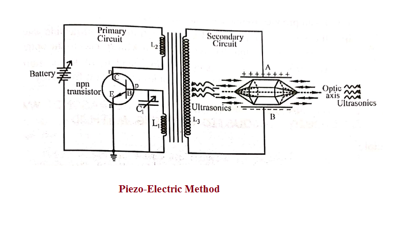
Construction
The
piezo‒electric generator consists of primary and secondary circuits. The
primary circuit is arranged with coils L1 and L2. The
coil L1 is connected to the base of the transistor and coil L2
is connected to the collector of the transistor. The capacitor C1 is
used to vary the frequency of the oscillatory circuit [L1C1].
The coil L2 is inductively coupled to the secondary circuit, which
comprises of the coil L3 and two metal plates A and B as shown in
Fig 5.6.
The
crystal is kept inbetween the plates A and B for the production of ultrasonics.
Necessary biasing, i.e., Emitter is forward biased ('n' is connected to
negative of the battery) and the collector is reverse biased ('n' is connected
to positive of the battery) is given with the help of the battery.

Working
The
battery is switched ON and hence current is produced by the transistor, in the
circuit. The current is passed through the coil L1 and L2
of the primary circuit. This current is transfered to the coil L3 in
the secondary circuit due to transformer action and is fed to the plates A and
B. Due to the principle of inverse piezo‒electric effect the crystal starts
vibrating along the mechanical axis of the crystal.
The
frequency of the oscillatory circuit is adjusted by the capacitor C1
and when this frequency is equal to the frequency of the vibrating crystal,
resonance occurs. At resonance the crystal vibrates vigorously and ultrasonic
waves are produced along both the ends of the crystal.
Condition for Resonance
Frequency
of the oscillatory circuit = Frequency of the vibrating crystal

(i.e.)
Where
l is the Length of the
crystal
E
is the Youngs modulus of the crystal
ρ
is the Density of the crystal
P
= 1,2,3.... etc. for fundamental, first over tone, second overtone etc.
respectively.
Limitations
(i)
It can produce frequency upto 500 MHz.
(ii)
It can produce longitudinal as well as transverse ultrasonic waves by properly
cutting and shaping the crystal with respect to the optic axis.
(iii)
The production of ultrasonics is independent of temperature and hence produces
high power ultrasonics at constant frequency.
Applied Physics I: Chapter 5: Oscillations and Waves - Ultrasonics : Tag: Applied Physics : Principle, Construction, Working, Condition, Limitations - Production of Ultrasonics - Piezo-Electric Effect and Piezo-Electric Method
Applied Physics I: Chapter 5: Oscillations and Waves - Ultrasonics
Under Subject

Applied Physics I
PH25C01 1st Semester | 2025 Regulation | 1st Semester 2025 Regulation
Related Subjects

English Essentials I
EN25C01 1st Semester | 2025 Regulation | 1st Semester 2025 Regulation

தமிழர் மரபு - Heritage of Tamils
UC25H01 1st Semester | 2025 Regulation | 1st Semester 2025 Regulation

Applied Calculus
MA25C01 Maths 1 M1 - 1st Semester | 2025 Regulation | 1st Semester 2025 Regulation
Applied Physics I
PH25C01 1st Semester | 2025 Regulation | 1st Semester 2025 Regulation

Applied Chemistry I
CY25C01 1st Semester | 2025 Regulation | 1st Semester 2025 Regulation

Makerspace
ME25C04 1st Semester | 2025 Regulation | 1st Semester 2025 Regulation

Computer Programming C
CS25C01 1st Semester | 2025 Regulation | 1st Semester 2025 Regulation

Computer Programming Python
CS25C02 1st Semester | 2025 Regulation | 1st Semester 2025 Regulation

Fundamentals of Electrical and Electronics Engineering
EE25C03 1st Semester | 2025 Regulation | 1st Semester 2025 Regulation

Introduction to Mechanical Engineering
ME25C03 1st Semester | 2025 Regulation | 1st Semester 2025 Regulation

Introduction to Civil Engineering
CE25C01 1st Semester Civil Department | 2025 Regulation | 1st Semester 2025 Regulation

Essentials of Computing
CS25C03 1st Semester - AID CSE IT Department | 2025 Regulation | 1st Semester 2025 Regulation

Applied Physics I Laboratory
PH25C01 1st Semester practical Laboratory Manual | 2025 Regulation | 1st Semester Laboratory 2025 Regulation

Applied Chemistry I Laboratory
CY25C01 1st Semester practical Laboratory Manual | 2025 Regulation | 1st Semester Laboratory 2025 Regulation

Computer Programming C Laboratory
CS25C01 1st Semester practical Laboratory Manual | 2025 Regulation | 1st Semester Laboratory 2025 Regulation

Computer Programming Python Laboratory
CS25C02 1st Semester practical Laboratory Manual | 2025 Regulation | 1st Semester Laboratory 2025 Regulation

Engineering Drawing
ME25C01 EEE Mech Dept | 2025 Regulation | 2nd Semester 2025 Regulation

Basic Electronics and Electrical Engineering
EE25C04 1st Semester ECE Dept | 2025 Regulation | 2nd Semester 2025 Regulation