Basic Electronics and Electrical Engineering: Chapter 8: Sensors and Transducers
Sensors and Transducers: Performance Terminology
Transducers or measurement systems are not perfect systems.
PERFORMANCE
TERMINOLOGY
Transducers or
measurement systems are not perfect systems. Mechatronics design engineer must
know the capability and shortcoming of a transducer or measurement system to
properly assess its performance. There are a number of performance related
parameters of a transducer or measurement system. These parameters are called
as sensor specifications.
Sensor specifications
in form the user to the about deviations from the ideal behavior of the
sensors. Following are the various specifications of a sensor/transducer
system.
1. Range
The range of a sensor
indicates the limits between which the input can vary. For example, a
thermocouple for the measurement of temperature might have a range of 25‒225°C.
2. Span
The span is difference
between the maximum and minimum values of the input. Thus, the above‒mentioned
thermocouple will have a span of 200°C.
3. Error
Error is the difference
between the result of the measurement and the true value of the quantity being
measured. A sensor might give a displacement reading of 29.8 mm, when the
actual displacement had been 30 mm, then the error is 0.2 mm.
4. Accuracy
The accuracy defines
the closeness of the agreement between the actual measurement result and a true
value of the measured. It is often expressed as a percentage of the full range
output or full‒scale deflection. A piezoelectric transducer used to evaluate
dynamic pressure phenomena associated with explosions, pulsations, or dynamic
pressure conditions in motors, rocket engines, compressors, and other pressurized
devices is capable to detect pressures between 0.1 and 10,000 psig (0.7 KPa to
70 MPa). If it is specified with the accuracy of about ± 1% full scale, then
the reading given can be expected to be within 0.7 MPa.
5. Sensitivity
Sensitivity of a sensor
is defined as the ratio of change in output value of a sensor to the per unit
change in input value that causes the output change. For example, a general
purpose thermocouple may have a sensitivity of 41 μ V/°C.
6. Nonlinearity
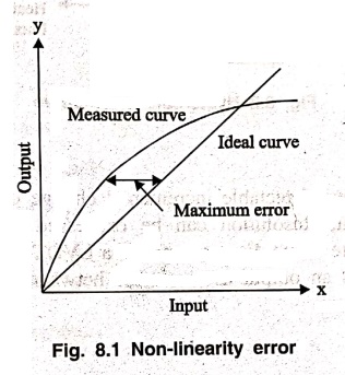
The nonlinearity
indicates the maximum deviation of the actual measured curve of a sensor from
the ideal curve. Figure 8.1 shows a somewhat exaggerated relationship between
the ideal, or least squares fit, line and the actual measured or calibration
line. Linearity is often specified in terms of percentage of nonlinearity,
which is defined as:
Nonlinearity (%) =
Maximum deviation in input / Maximum full scale input
The static nonlinearity
defined by Equation is dependent upon environmental factors, including
temperature, vibration, acoustic noise level, and humidity. Therefore it is
important to know under what conditions the specification is valid.
7. Hysteresis
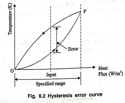
The hysteresis is an
error of a sensor, which is defined as the maximum difference in output at any
measurement value within the sensor's specified range when approaching the point
first with increasing and then with decreasing the input parameter. Fig. 8.2
shows the hysteresis error might have occurred during measurement of
temperature using a thermocouple. The hysteresis error value is normally
specified as a positive or negative percentage of the specified input range.
8. Resolution
Resolution is the
smallest detectable incremental change of input parameter that can be detected
in the output signal. Resolution can be expressed either as a proportion of the
full‒scale reading or in absolute terms. For example, if a LVDT sensor measures
a displacement up to 20 mm and it provides an output as a number between 1 and
100 then the resolution of the sensor device is 0.2 mm.
9. Stability
Stability is the
ability of a sensor device to give same output when used to measure a constant
input over a period of time. The term "drift" is used to indicate the
change in output that occurs over a period of time. It is expressed as the
percentage of full range output.
10. Deadband/time
The dead band or dead
space of a transducer is the range of input values for which There is no
output. The dead time of a sensor device is the time duration from the
application of an input until the output begins to respond or change.
11. Repeatability
It specifies the
ability of a sensor to give same output for repeated applications of same input
value. It is usually expressed as a percentage of the full range output:
Repeatability =
(maximum ‒ minimum values given) × 100 / full range
12. Response time
Response time describes
the speed of change in the output on a step‒wise change of the measurand. It is
always specified with an indication of input step and the output range for
which the response time is defined.
Basic Electronics and Electrical Engineering: Chapter 8: Sensors and Transducers : Tag: Basic Engineering : - Sensors and Transducers: Performance Terminology
Basic Electronics and Electrical Engineering: Chapter 8: Sensors and Transducers
Under Subject

Basic Electronics and Electrical Engineering
EE25C04 1st Semester ECE Dept | 2025 Regulation | 2nd Semester 2025 Regulation
Related Subjects

English Essentials I
EN25C01 1st Semester | 2025 Regulation | 1st Semester 2025 Regulation

தமிழர் மரபு - Heritage of Tamils
UC25H01 1st Semester | 2025 Regulation | 1st Semester 2025 Regulation

Applied Calculus
MA25C01 Maths 1 M1 - 1st Semester | 2025 Regulation | 1st Semester 2025 Regulation
Applied Physics I
PH25C01 1st Semester | 2025 Regulation | 1st Semester 2025 Regulation

Applied Chemistry I
CY25C01 1st Semester | 2025 Regulation | 1st Semester 2025 Regulation
Makerspace
ME25C04 1st Semester | 2025 Regulation | 1st Semester 2025 Regulation
Computer Programming C
CS25C01 1st Semester | 2025 Regulation | 1st Semester 2025 Regulation
Computer Programming Python
CS25C02 1st Semester | 2025 Regulation | 1st Semester 2025 Regulation
Fundamentals of Electrical and Electronics Engineering
EE25C03 1st Semester | 2025 Regulation | 1st Semester 2025 Regulation
Introduction to Mechanical Engineering
ME25C03 1st Semester | 2025 Regulation | 1st Semester 2025 Regulation

Introduction to Civil Engineering
CE25C01 1st Semester Civil Department | 2025 Regulation | 1st Semester 2025 Regulation
Essentials of Computing
CS25C03 1st Semester - AID CSE IT Department | 2025 Regulation | 1st Semester 2025 Regulation

Applied Physics I Laboratory
PH25C01 1st Semester practical Laboratory Manual | 2025 Regulation | 1st Semester Laboratory 2025 Regulation

Applied Chemistry I Laboratory
CY25C01 1st Semester practical Laboratory Manual | 2025 Regulation | 1st Semester Laboratory 2025 Regulation

Computer Programming C Laboratory
CS25C01 1st Semester practical Laboratory Manual | 2025 Regulation | 1st Semester Laboratory 2025 Regulation

Computer Programming Python Laboratory
CS25C02 1st Semester practical Laboratory Manual | 2025 Regulation | 1st Semester Laboratory 2025 Regulation
Engineering Drawing
ME25C01 EEE Mech Dept | 2025 Regulation | 2nd Semester 2025 Regulation
Basic Electronics and Electrical Engineering
EE25C04 1st Semester ECE Dept | 2025 Regulation | 2nd Semester 2025 Regulation