Basic Electronics and Electrical Engineering: Chapter 8: Sensors and Transducers
Displacement and Position Sensors
1. Potentiometer Sensors 2. Strain Gauges 3. Capacitive element based sensor 4. Linear variable differential transformer (LVDT) 5. Eddy current proximity sensors 6. Inductive proximity switch 7. Optical encoders 8. Pneumatic sensors
DISPLACEMENT
AND POSITION SENSORS
Displacement sensors
are basically used for the measurement of movement of an object. Position
sensors are employed to determine the position of an object in relation to some
reference point.
Proximity sensors are a
type of position sensor and are used to trace when an object has moved with in
particular critical distance of a transducer.
1. Potentiometer Sensors
Figure shows the
construction of a rotary type potentiometer sensor employed to measure the
linear displacement. The potentiometer can be of linear or angular type. It
works on the principle of conversion of mechanical displacement into an
electrical signal.

The sensor has a resistive
element and a sliding contact (wiper). The slider moves along this conductive
body, acting as a movable electric contact.
The object of whose
displacement is to be measured is connected to the slider by using
• a rotating shaft (for
angular displacement)
• a moving rod (for
linear displacement)
• a cable that is kept
stretched during operation The resistive element is a wire wound track or
conductive plastic. The track comprises of large number of closely packed turns
of a resistive wire. Conductive plastic is made up of plastic resin embedded dc
with the carbon powder. Wire wound track has a resolution of the order of ±0.01
% while the conductive plastic may have the resolution of about 0.1% m.
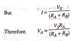
During the sensing
operation, a voltage Vs is applied across the resistive element. A voltage
divider circuit is formed when slider comes into contact with the wire. The
output voltage (VA) is measured as shown in the figure 8.4. The
output voltage is proportional to the displacement of the slider over the wire.
Then the output parameter displacement is calibrated against the output voltage
VA.

VA = IRA
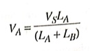
As we know that R = ρL
/ A, where ρ is electrical resistivity, L is length of resistor and A is area
of cross section
VA = (VSLA) /
(LA+LB)
Applications of potentiometer
These sensors are
primarily used in the control systems with a feedback loop to ensure that the
moving member or component reaches its commanded position.
These are typically
used on machine‒tool controls, elevators, liquid‒level assemblies. forklift
trucks, automobile throttle controls. In manufacturing, these are used in
control of injection molding machines, wood working machinery, printing,
spraying, robotics, etc.
2. Strain Gauges
The strain in an
element is a ratio of change in length in the direction of applied load to the
original length of an element. The strain changes the resistance R of the
element. Therefore, we can say,
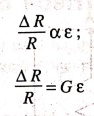
∆R/R α ε
∆R/R = Gε
where G is the constant
of proportionality and is called as gauge factor. In general, the value of G is
considered in between 2 to 4 and there resistances are taken of the order of
100 Ω.
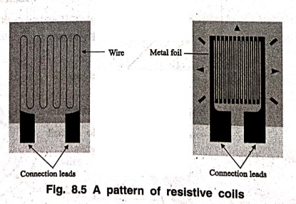
Resistance strain gauge
follows the principle of change in resistance as per the equation. It comprises
of a pattern of resistive foil arranged as shown in Figure 8.5.These foils are
made of Constant an alloy (copper‒nickel 155‒45% alloy) and are bonded to a
backing material plastic (polyamide), epoxy or glass fiber reinforced epoxy.
The strain gauges are
secured to the workpiece by using epoxy or Cyanoacrylate cement Eastman 910 SL.
As the workpiece undergoes change in its shape due to external loading, the
resistance of strain gauge element changes. This change in resistance can be
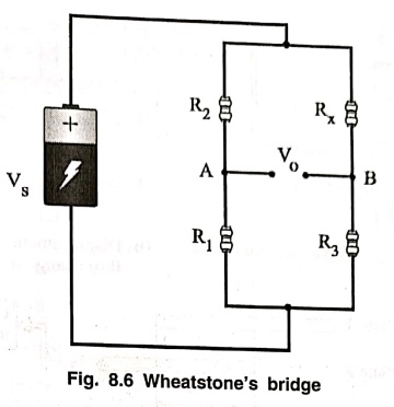
detected by a using a Wheatstone's resistance bridge as shown in Figure 8.6. In
the balanced bridge we can have a relation,
R2/R1
= Rx/R3
Where Rx is
resistance of strain gauge element, R2 is balancing/adjustable
resistor, R1 and R3 known constant value resistors. The
measured deformation or displacement by the stain gauge is calibrated against
change in resistance of adjustable resistor R2 which makes the
voltage across nodes A and B equal to zero.
Applications of strain gauge
Strain gauges are
widely used in experimental stress analysis and diagnosis on machines and
failure analysis. They are basically used for multi‒axial stress fatigue
testing, proof testing, residual stress and vibration measurement, torque
measurement, bending and deflection measurement, compression and tension
measurement and strain measurement.
Strain gauges are
primarily used as sensors for machine tools and safety in automotives. In
particular, they are employed for force measurement in machine tools, hydraulic
or pneumatic press and as impact sensors in aerospace vehicles.
3. Capacitive element based sensor
Capacitive sensor is of
non‒contact type sensor and is primarily used to measure the linear
displacements from few millimeters to hundreds of millimeters. It comprises of
three plates, with the upper pair forming one capacitor and the lower pair
another.
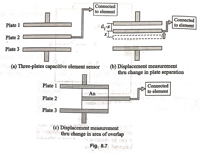
The linear displacement
might take in two forms:
(a) one of the plates
is moved by the displacement so that the plate separation changes
(b) Area of overlap
changes due to the displacement.
Figure 8.7 shows the
schematic of three‒plate capacitive element sensor and displacement measurement
of a mechanical element connected to the plate 2.
The capacitance C of a
parallel plate capacitor is given by, C = εrε0 A/d
Where εr is the relative permittivity of the
dielectric between the plates, ε0 permittivity of free space, A area
of overlap between two plates and d
the plate separation.
As the central plate
moves near to top plate or bottom one due to the movement of the
element/workpiece of which displacement is to be measured, separation in
between the plate changes. This can be given as,

When C1 and
C2 are connected are connected to a Wheatsone's bridge, then the
resulting out‒of -balance voltage would be in proportional to displacement x.
Capacitive elements can
also be used as proximity sensor. The approach of the object towards the sensor
plate is used for induction of change in plate separation. This changes the
capacitance which is used to detect the object.
Applications of capacitive element sensors
• Feed hopper level
monitoring
• Small vessel pump
control
• Grease level
monitoring
• Level control of
liquids
• Metrology
applications
• to measure shape
errors in the part being produced
• to analyze and
optimize the rotation of spindles in various machine tools such as surface
grinders, lathes, milling machines, and air bearing spindles by measuring
errors in the machine tools themselves
• Assembly line testing
• to test assembled
parts for uniformity, thickness or other design features
• to‒detect to detect
the presence or absence of a certain component, such as glue etc.
4. Linear variable differential transformer (LVDT)
Linear variable
differential transformer (LVDT) is a primary transducer used for measurement of
linear displacement with an input range of about 2 to 400 mm in general. It has
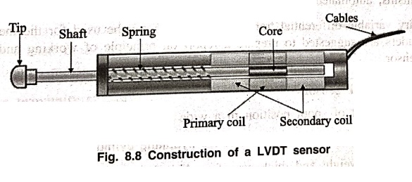
non‒linearity error 0.25% of full range. Figure 8.9 shows the construction of a
LVDT sensor. It has three coils symmetrically spaced along an insulated tube.
The central coil is primary coil and the other two are secondary coils.
Secondary coils are connected in series in such a way that their outputs oppose
each other. A magnetic core attached to the element of which displacement is to
be monitored is placed inside the insulated tube,
Due to an alternating
voltage input to the primary coil, alternating electro‒magnetic forces (emfs)
are generated in secondary coils.
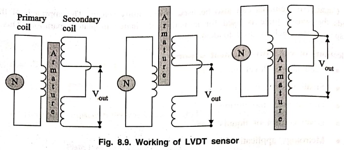
When the magnetic core
is centrally placed with its half portion in each of the secondary coil regions
then the resultant voltage is zero. If the core is displaced from the central
position as shown in Figure 8.9 say, more in secondary coil 1 than in coil 2,
then more emf is generated in one coil i.e. coil 1 than the other, and there is
a resultant voltage from the coils. If the magnetic core is further displaced,
then the value of resultant voltage increases in proportion with the
displacement. With the help of signal processing devices such as low‒pass
filters and demodulators, precise displacement can be measured by using LVDT
sensors.
LVDT exhibits good
repeatability and reproducibility. It is generally used as an absolute position
sensor. Since there is no contact or sliding between the constituent elements
of the sensor, it is highly reliable. These sensors are completely sealed and
are w widely used in Servomechanisms, automated measurement in machine tools.
A rotary variable
differential transformer (RVDT) can be used for the measurement of rotation.
Readers are suggested to prepare a report on principle of working and
construction of RVDT sensor.
Applications of LVDT sensors
• Measurement of spool
position in a wide range of servo valve applications
• To provide
displacement feedback for hydraulic cylinders
• To control weight and
thickness of medicinal products viz. tablets or pills
• For automatic
inspection of final dimensions of products being packed for dispatch
• To measure distance
between the approaching metals during Friction welding process
• To continuously
monitor fluid level as part of leak detection system
• To detect the number
of currency bills dispensed by an ATM.
5. Eddy current proximity sensors
Eddy current proximity
sensors are used to detect non‒magnetic but conductive materials. They comprise
of a coil, an oscillator, a detector and a triggering circuit. Figure 8.10
shows the construction of eddy current proximity switch.
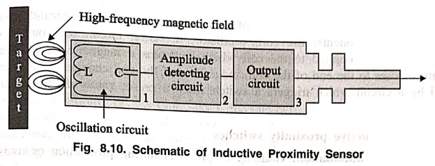
When an alternating
current is passed through this coil, an alternative magnetic field is
generated. If a metal object comes in the close proximity of the coil, then
eddy currents are induced in the object due to the magnetic field. These eddy
currents create their own magnetic field which distorts the magnetic field
responsible for their generation. As a result, impedance of the coil changes
and so the amplitude of alternating current. This can be used to trigger a
switch at some pre‒determined level of change in current.
Eddy current sensors
are relatively inexpensive, available in small in size, highly reliable and
have high sensitivity for small displacements.
Applications of eddy current proximity sensors
• Automation requiring
precise location
• Machine tool
monitoring
• Final assembly of
precision equipment such as disk drives
• Measuring the
dynamics of a continuously moving target, such as a vibrating element,
• Drive shaft
monitoring
• Vibration
measurements
6. Inductive proximity switch
Inductive proximity
switches are basically used for detection of metallic objects.

Figure 8.11 shows the
construction of inductive proximity switch. An inductive proximity sensor has
four components; the coil, oscillator, detection circuit and output circuit. An
alternating current is supplied to the coil which generates a magnetic field.
When, a metal object comes closer to the end of the coil, inductance of the
coil changes. This is continuously monitored by a circuit which triggers a
switch when a preset value of inductance change is occurred.
Applications of inductive proximity switches
•
Industrial automation: counting of products during
production or transfer.
•
Security: detection of metal objects, arms, landmines.
7. Optical encoders

Optical encoders
provide digital output as a result of linear / angular displacement. These are
widely used in the Servomotors to measure the rotation of shafts. Figure 8.12 shows
the construction of an optical encoder. It comprises of a disc with three
concentric tracks of equally spaced holes. Three light sensors are employed to
detect the light passing through the holes. These sensors produce electric
pulses which give the angular displacement of the mechanical element e.g. shaft
on which the Optical encoder is mounted. The inner track has just one hole
which is used locate the position of the disc. The holes on the middle track
offset from the holes of the outer track by one‒half of the width of the hole.
This arrangement provides the direction of rotation to be determined. When the
disc rotates in clockwise direction, the pulses in the outer track lead those
in the inner; in counter clockwise direction they lag behind. The resolution
can be determined by the number of holes on disc. With 100 holes in one
revolution, the resolution would be,
360° / 100 = 3.6°
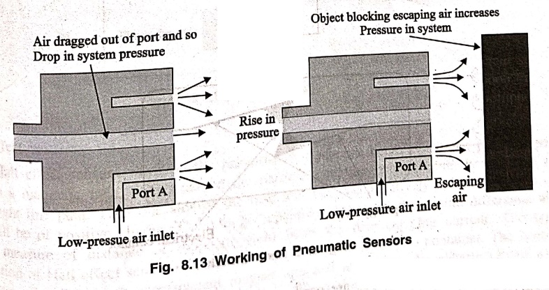
8. Pneumatic sensors
Pneumatic sensors are
used to measure the displacement as well as to sense the proximity of an object
close to it. The displacement and proximity are transformed into change in air
pressure. Figure 8.23. Shows a schematic of construction and working of such a
sensor. It comprises of three ports. Low pressure air is allowed to escape
through port A. In the absence of any obstacle / object, this low pressure air
escapes and in doing so, reduces the pressure in the port B. However when an
object obstructs the low pressure air (Port A), there is rise in pressure in
output port B. This rise in pressure is calibrated to measure the displacement
or to trigger a switch. These sensors are used in robotics, pneumatics and for
tooling in CNC machine tools.
Basic Electronics and Electrical Engineering: Chapter 8: Sensors and Transducers : Tag: Basic Engineering : - Displacement and Position Sensors
Basic Electronics and Electrical Engineering: Chapter 8: Sensors and Transducers
Under Subject

Basic Electronics and Electrical Engineering
EE25C04 1st Semester ECE Dept | 2025 Regulation | 2nd Semester 2025 Regulation
Related Subjects

English Essentials I
EN25C01 1st Semester | 2025 Regulation | 1st Semester 2025 Regulation

தமிழர் மரபு - Heritage of Tamils
UC25H01 1st Semester | 2025 Regulation | 1st Semester 2025 Regulation

Applied Calculus
MA25C01 Maths 1 M1 - 1st Semester | 2025 Regulation | 1st Semester 2025 Regulation

Applied Physics I
PH25C01 1st Semester | 2025 Regulation | 1st Semester 2025 Regulation

Applied Chemistry I
CY25C01 1st Semester | 2025 Regulation | 1st Semester 2025 Regulation

Makerspace
ME25C04 1st Semester | 2025 Regulation | 1st Semester 2025 Regulation

Computer Programming C
CS25C01 1st Semester | 2025 Regulation | 1st Semester 2025 Regulation

Computer Programming Python
CS25C02 1st Semester | 2025 Regulation | 1st Semester 2025 Regulation

Fundamentals of Electrical and Electronics Engineering
EE25C03 1st Semester | 2025 Regulation | 1st Semester 2025 Regulation

Introduction to Mechanical Engineering
ME25C03 1st Semester | 2025 Regulation | 1st Semester 2025 Regulation

Introduction to Civil Engineering
CE25C01 1st Semester Civil Department | 2025 Regulation | 1st Semester 2025 Regulation

Essentials of Computing
CS25C03 1st Semester - AID CSE IT Department | 2025 Regulation | 1st Semester 2025 Regulation

Applied Physics I Laboratory
PH25C01 1st Semester practical Laboratory Manual | 2025 Regulation | 1st Semester Laboratory 2025 Regulation

Applied Chemistry I Laboratory
CY25C01 1st Semester practical Laboratory Manual | 2025 Regulation | 1st Semester Laboratory 2025 Regulation

Computer Programming C Laboratory
CS25C01 1st Semester practical Laboratory Manual | 2025 Regulation | 1st Semester Laboratory 2025 Regulation

Computer Programming Python Laboratory
CS25C02 1st Semester practical Laboratory Manual | 2025 Regulation | 1st Semester Laboratory 2025 Regulation

Engineering Drawing
ME25C01 EEE Mech Dept | 2025 Regulation | 2nd Semester 2025 Regulation
Basic Electronics and Electrical Engineering
EE25C04 1st Semester ECE Dept | 2025 Regulation | 2nd Semester 2025 Regulation