Applied Physics I: Chapter 8: Applied Optics - Interference
Theory of Michelson's interferometer and Types of fringes
Principle, Construction, Working, Adjustments
THEORY OF MICHELSON'S INTERFEROMETER: Principle, Construction, Working, Adjustments. TYPES OF FRINGES: (i) Circular fringes (ii) Localised fringes iii) Localised white light fringes
INTERFEROMETRY
The
phenomenon of interference has been used to test the flatness of surfaces and
also used to reduce the reflecting power of the lens and prisms. Instruments based on the principle of
interference of light are known as interferometers. Michelson designed an
interferometer to determine the wavelength of the light, resolution of the
spectral line and the thickness of the thin transparent materials.
THEORY OF MICHELSON'S INTERFEROMETER
Principle
The
amplitude of light beam from a source is divided into two parts of equal
intensities by partial reflection and transmission. These beams are then sent
in two directions at right angles and are brought together after they suffer
reflection from plane mirrors to produce interference fringes.
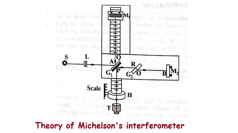
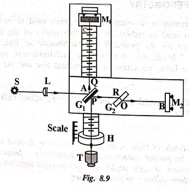
Construction
The
Schematic diagram of a Michelson interferometer is as shown in Fig. 8.9. It
consists of two highly polished plane mirrors M1 and M2
which are at right angles to each other. There are two optically flat glass
plates G1 and G2 of same thickness and made up of same
material placed parallel to each other. These plates are inclined at an angle
of 45° with the mirrors M1 and M2.
The
plate G1 is half silvered at the back so that the incident beam is
divided into two beams viz., reflected beam and transmitted beam of equal
intensity. The mirrors M1 and M2 are provided with screws
on their backs, so that they can be adjusted exactly perpendicular to each
other.
The
mirror M1 is mounted on a carriage which can be moved forward and
backward using the handle 'H'. The distance at which the M1 is moved
can be read with the help of the scale as shown in Fig. 8.9. The interference
fringes can be observed in the field of view of the telescope 'T'.
Working
Light
from a monochromatic source S is made parallel with the help of collimating
lens L. The light beam is allowed to fall on the semisilvered glass plate G1.
It is partly reflected at the back surface of G1 and travel towards
M1 i.e. along (AC) and partly transmitted towards M2
(i.e. along AB). These two rays travel along two mutually perpendicular paths
and are reflected back by the mirror M1 and M2. These two
rays again meet at glass plate G1 and enter a short focus telescope
T.
The
two rays which enter the telescope are originally derived from the same single
beam, hence they cause the interference fringes in the field to view of the
telescope. Hence a path difference can be introduced between the two reflected
rays by moving the mirror M1.
It
is clear from the Fig.8.9 that a ray PC passes twice through the glass plate G1
i.e., 1st through PQ and 2nd through QP, after reflection from the mirror M1,
whereas the ray PB does not even passes once through G1, even after
reflection from the mirror M2. Thus in the absence of the glass
plate G2 the path traced by the beam between G1M1
and G1M2 are not equal.
To
equalise the path difference, a glass plate G2 of same thickness and
material as that of G1 is introduced between G1 and M2.
So that the ray PB will also pass twice, i.e., 1st through RO in
glass plate G2 and 2nd through OR in glass plate G2,
after reflection from the mirror M2.
Since
the glass plate G2 is used to compensate the path difference between
the two rays, it is called as a compensation plate. Thus the path of the two
rays viz., PB and PC are made equal.
Adjustments
(i)
The distance of the mirrors M1 and M2 are adjusted to be
nearly equal from G1.
(ii)
In order to make the incident beam parallel, a tin sheet with a small hole is
placed in front of source S.
(iii)
The hole and the light from the source are adjusted in line with the centre of
glass plates G1 and G2 and mirror M2.
(iv)
A lens is then placed between G1 and tin sheet and a plane mirror is
placed between G1 and lens normally.
(v)
The lens position is adjusted till the image of the hole falls back on the tin
plate very close to the hole, hence the light is made as a parallel beam when
it leaves the lens.
(vi)
If the plane mirror is removed, and if the beam is seen in the direction of AT.
We can see four images of the hole. The mirrors are adjusted till the images
coincide two by two.
(vii)
At this stage, if the tin sheet is removed, then the two paths of light are
exactly parallel to each other giving rise to circular fringes in the field of
view. By tilting mirror M2 slightly, the fringes can be made
straight.
TYPES OF FRINGES
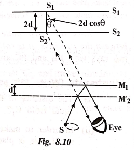
(i) Circular fringes
When
mirror M2 is exactly perpendicular to mirror M1 and the
virtual mirror M2' (which is image of M2) an air film of
constant thickness is enclosed between them as shown in Fig. 8.10.
The
airfilm gives reflected beam to interface. The path difference depends upon the
following factors.
(i)
The separation between M1 and M2'
(ii)
The angle subtended on the eye
(iii)
The inclination between M1 and M2'
It
can be seen from the Fig. 8.10 that the path differences are different for
different values of θ. The source S is an extended source and S1 and
S2 are the virtual source due to M1 and M2'.
If the distance between M1 and M2' is d and the distance
between S1 and S2 is 2d, then
The
path difference between the two rays = 2dcosθ
Since
the light reflected from mirror M2 is again reflected by the semi‒silvered
glass plate G1, an additional path difference of λ/2 has to be
introduced.
Therefore,
the total path difference between the two rays = 2dcosθ + λ/2
If
the total path difference is = nλ, we get bright fringes and
If
the total path difference is = (2n+1) λ/2, we get dark fringes.
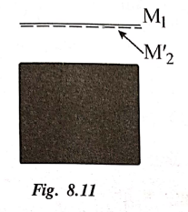
Case
i)
When M1 and M2' coincides, the path difference is zero
and therefore the field of view is perfectly dark, as shown in Fig. 8.11.
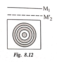
Case
ii)
When M1 is moved either way parallel to itself, widely spaced
circular fringes are produced. The width of the fringes depends upon the path
difference between the rays. (Fig 8.12)
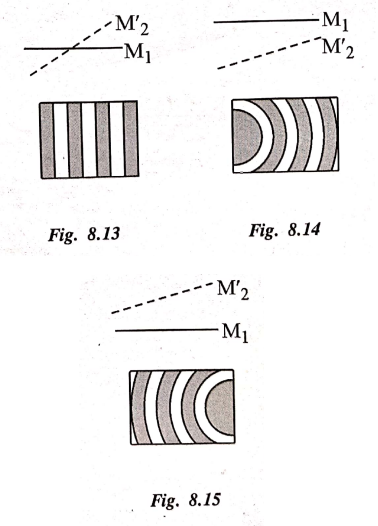
(ii) Localised fringes
When
the mirror M2 is not exactly perpendicular to M1 (or) if
M1 and the virtual mirror M2' are inclined, then the
airfilm enclosed between them is wedge shaped.
For
small path difference, the fringes are nearly straight but for large path
difference the fringes are generally curved and are always covex towards the
thin edge of the wedge. When the two mirrors M1 and M2'
middle, straight line fringes are observed as shown in Fig. 8.13. When the two
mirrors are inclined, curved fringes are observed as shown in Fig. 8.14 and
8.15.
iii) Localised white light fringes
With
white light, the fringes are observed only when the path difference is very
small. The fringes of zero thickness is dark (i.e) central fringe and the other
fringes are coloured due to overlapping of various colours. If the film is
thick, uniform illumination is observed. White light fringes are useful to find
the zero path difference, especially in the standardisation of metre.
Applied Physics I: Chapter 8: Applied Optics - Interference : Tag: Applied Physics : Principle, Construction, Working, Adjustments - Theory of Michelson's interferometer and Types of fringes
Applied Physics I: Chapter 8: Applied Optics - Interference
Under Subject

Applied Physics I
PH25C01 1st Semester | 2025 Regulation | 1st Semester 2025 Regulation
Related Subjects

English Essentials I
EN25C01 1st Semester | 2025 Regulation | 1st Semester 2025 Regulation

தமிழர் மரபு - Heritage of Tamils
UC25H01 1st Semester | 2025 Regulation | 1st Semester 2025 Regulation

Applied Calculus
MA25C01 Maths 1 M1 - 1st Semester | 2025 Regulation | 1st Semester 2025 Regulation
Applied Physics I
PH25C01 1st Semester | 2025 Regulation | 1st Semester 2025 Regulation

Applied Chemistry I
CY25C01 1st Semester | 2025 Regulation | 1st Semester 2025 Regulation

Makerspace
ME25C04 1st Semester | 2025 Regulation | 1st Semester 2025 Regulation

Computer Programming C
CS25C01 1st Semester | 2025 Regulation | 1st Semester 2025 Regulation

Computer Programming Python
CS25C02 1st Semester | 2025 Regulation | 1st Semester 2025 Regulation

Fundamentals of Electrical and Electronics Engineering
EE25C03 1st Semester | 2025 Regulation | 1st Semester 2025 Regulation

Introduction to Mechanical Engineering
ME25C03 1st Semester | 2025 Regulation | 1st Semester 2025 Regulation

Introduction to Civil Engineering
CE25C01 1st Semester Civil Department | 2025 Regulation | 1st Semester 2025 Regulation

Essentials of Computing
CS25C03 1st Semester - AID CSE IT Department | 2025 Regulation | 1st Semester 2025 Regulation

Applied Physics I Laboratory
PH25C01 1st Semester practical Laboratory Manual | 2025 Regulation | 1st Semester Laboratory 2025 Regulation

Applied Chemistry I Laboratory
CY25C01 1st Semester practical Laboratory Manual | 2025 Regulation | 1st Semester Laboratory 2025 Regulation

Computer Programming C Laboratory
CS25C01 1st Semester practical Laboratory Manual | 2025 Regulation | 1st Semester Laboratory 2025 Regulation

Computer Programming Python Laboratory
CS25C02 1st Semester practical Laboratory Manual | 2025 Regulation | 1st Semester Laboratory 2025 Regulation

Engineering Drawing
ME25C01 EEE Mech Dept | 2025 Regulation | 2nd Semester 2025 Regulation

Basic Electronics and Electrical Engineering
EE25C04 1st Semester ECE Dept | 2025 Regulation | 2nd Semester 2025 Regulation