Basic Electronics and Electrical Engineering: Practical Experimentation
To Study the Construction and Working Principle of DC Machines
All the generators work on a principle of dynamically induced e.m.f.
To
Study the Construction and Working Principle of DC Machines
Principle of Operation of a D.C. Generator
All the generators work
on a principle of dynamically induced e.m.f. This principle nothing but the
Faraday's law of electromagnetism induction it sates that, whenever the number
of magnetic lines of force i.e. flux linking with a conductor or a coil
changes, an electromotive force is set up in that conductor or coil. The change
in flux associated with the conductor can exist only when there exists a
relative motion between a conductor and the flux. The relative motion can be
achieved by rotating conductor with respect to flux or by rotating flux with
respect to a conductor. So a voltage gets generated in a conductor, as long as
there exists a relative motion between conductor and the flux. Such an induced
e.m.f. which is due to the physical movement of coil or conductor with respect
to flux or movement of flux with respect to coil or conductor is called dynamically
induced e.m.f.
Key Point
So a generating action
requires following basic components to exist,
(i) The conductor or a
coil
(ii) The relative
motion between conductor and flux.
In a particular
generator, the conductors are rotated to cut the magnetic flux, keeping flux
stationary. To have a large voltage as the output, the number of conductors are
connected together in a specific manner, to form a winding. This winding is
called armature winding of a d.c. machine. The part on which this winding is kept
is called armature of a d.c. machine. To have the rotation of conductors, the
conductors placed on the armature are rotated with the help of some external
device. Such an external device is called a prim mover. The commonly used prim
movers are diesel engines, steam engines, steam turbines, water turbines etc.
The necessary magnetic flux is produced by current carrying winding which is
called field winding. The direction of the induced e.m.f. can be obtained by
using Single Loop DC Generator.
Single Loop DC Generator
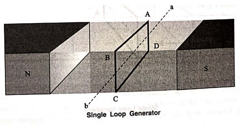
In the figure above, a
single loop of conductor of rectangular shape is placed between two opposite
poles of magnet. Let's us consider, the rectangular loop of conductor is ABCD
which rotates inside the magnetic field about its own axis ab. When the loop
rotates from its vertical position to its horizontal position, it cuts the flux
lines of the field. As during this movement two sides, i.e. AB and CD of the
loop cut the flux lines there will be an emf induced in these both of the sides
(AB and BC) of the loop.
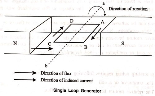
As the loop is closed
there will be a current circulating through the loop. The direction of the
current can be determined by Flemming's right hand Rule. This rule says that if
you stretch thumb, index finger and middle finger of your right hand
perpendicular to each other, then thumbs indicates the direction of motion of
the conductor, index finger indicates the direction of magnetic field i.e. N‒pole.
to S‒pole, and middle finger indicates the direction of flow of current through
the conductor.

Now if we apply this
right hand rule, we will see at this horizontal position of the loop, current
will flow from point A to B and on the other side of the loop current will flow
from point C to D.
Now if we allow the
loop to move further, it will come again to its vertical position, but now
upper side of the loop will be CD and lower side will be AB (just opposite of
the previous vertical position). At this position the tangential motion of the
sides of the loop is parallel to the flux lines of the field. Hence there will
be no question of flux cutting and consequently there will be no current in the
loop. If the loop rotates further, it comes to again in horizontal position.
But now, said AB side of the loop comes in front of N pole and CD comes in
front of S pole, i.e. just opposite to the previous horizontal position as
shown in the figure beside.
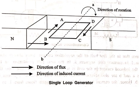
Here the tangential
motion of the side of the loop is perpendicular to the flux lines, hence rate
of flux cutting is maximum here and according to Flemming's right hand Rule, at
this position current flows from B to A and on other side from D to C. Now if
the loop continued to rotate about its axis, every time the side AB comes in
front of S pole, the current flows from A to B and when it comes in front of N
pole, the current flows from B to A. Similarly, every time the side CD comes in
front of S pole the current flows from C to D and when it comes in front of N
pole the current flows from D to C.
If we observe this
phenomena in different way, it can be concluded, that each side of the loop
comes in front of N pole, the current will flow through that side in same
direction ie, downward to the reference plane and similarly each side of the
loop comes in front of S pole, current through it flows in same direction i.e.
upwards from reference plane. From this, we will come to the topic of principle
of DC generator. Now the loop is opened and connected it with a split ring as
shown in the figure below. Split ring are made out of conducting cylinder which
cuts into two halves or segments insulated from each other. The external load
terminals are connected with two carbon brushes which are rest on these split
slip ring segments.
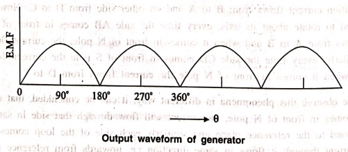
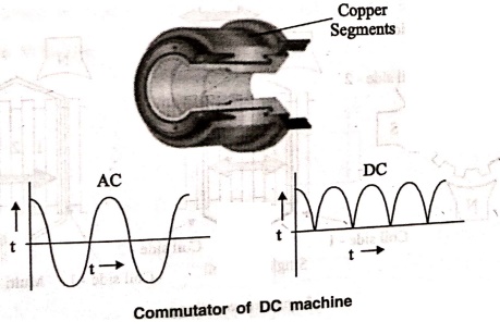
Working Principle of DC Generator
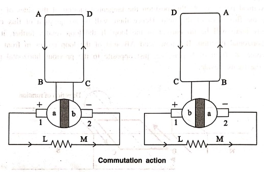
It is seen that in the
first half of the revolution current flows always along ABLMCD i.e. brush no 1
in contact with segment a. In the next half revolution, in the figure the
direction of the induced current in the coil is reversed. But at the same time
the position of the segments a and b are also reversed which results that brush
no 1 comes in touch with the segment b. Hence, the current in the load
resistance again flows from L to M. The wave from of the current through the
load circuit is as shown in the figure. This current is unidirectional.
This is basic working
principle of DC generator, explained by single loop generator model. The
position of the brushes of DC generator is so arranged that the change over of
the segments a and b from one brush to other takes place when the plane of
rotating coil is at right angle to the plane of the lines of force. It is so
become in that position, the induced emf in the coil is zero.
Construction of a DC Machine
A DC generator can be
used as a DC motor without any constructional changes and vice versa is also
possible. Thus, a DC generator or a DC motor can be broadly termed as a DC
machine. These basic constructional details are also valid for the construction
of a DC motor. Hence, let's call this point as construction of a DC machine
instead of just 'construction of a DC generator.
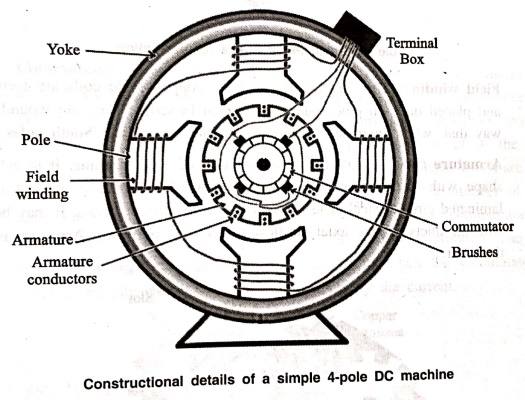
The above figure shows
constructional details of a simple 4‒pole DC machine. A DC machine consists of
two basic parts; stator and rotor. Basic constructional parts of a DC machine
are described below.
1.
Yoke: The outer frame of a dc machine is called as yoke.
It is made up of cast iron or steel. It not only provides mechanical strength
to the whole assembly but also carries the magnetic flux produced by the field
winding.
2.
Poles and pole shoes: Poles are joined to the yoke with the
help of bolts or welding. They carry field winding and pole shoes are fastened
to them. Pole shoes to serve two purposes; (i) they support field coils and
(ii) spread out the flux in air gap uniformly.

3.
Field winding: They are usually made of copper. Field
coils are former wound and placed on each pole and are connected in series.
They are wound in such a way that, when energized, they form alternate North
and South poles.
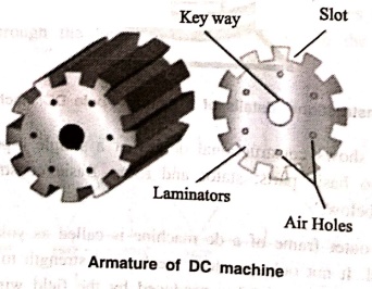
4.
Armature core: Armature core is the rotor of a dc
machine. It is cylindrical in shape with slots to carry armature winding. The
armature is built up of thin laminated circular steel disks for reducing eddy
current losses: It may be provided with air ducts for the axial air flow for
cooling purposes. Armature is keyed to the shaft.
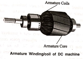
5.
Armature winding: It is usually a former wound copper coil
which rests in armature slots. The armature conductors are insulated from each
other and also from the armature core. Armature winding can be wound by one of
the two methods; lap winding or wave winding. Double layer lap or wave windings
are generally used. A double layer winding means that each armature slot will
carry two different coils.
6.
Commutator and brushes: Physical connection to the
armature winding is made through a commutator‒brush arrangement. The function
of a commutator, in a dc generator, is to collect the current generated in
armature conductors. Whereas, in case of a dc motor, commutator helps in
providing current to the armature conductors. A commutator consists of a set of
copper segments which are insulated from each other. The number of segments is
equal to the number of armature coils. Each segment is connected to an armature
coil and the commutator is keyed to the shaft. Brushes are usually made from
carbon or graphite. They rest on commutator segments and slide on the segments
when the commutator rotates keeping the physical contact to collect or supply
the current.
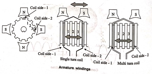
Armature Winding Terminology
Now we are going to
discuss about armature winding in details. Before going through this section,
we should understand some basic terms related to armature winding of DC generator.
Pole Pitch
The pole pitch is
defined as peripheral distance between centers of two adjacent poles in DC
machine. This distance is measured in term of armature slots or armature
conductor come between two adjacent pole centers. Pole Pitch is naturally equal
to the total number of armature slots divided by the number of poles in the
machine.
If there are 96 slots
on the armature periphery and 4 numbers of poles in the machine. the numbers of
armature slots come between two adjacent poles centres would be 96/4 = 24.
Hence, the pole pitch of that DC machine would be 24. As we have seen that,
pole pitch is equal to total numbers of armature slots divided by total numbers
of poles, we alternatively refer it as armature slots per pole.
Coil side
Coil of dc machine is
made up of one turn or multi turns of the conductor. If the coil is made up of
single turn or a single loop of conductor, it is called single turn coil. If
the coil is made up of more than one turn of a conductor, we refer it as a
multi‒turn coil. A single turn coil will have one conductor per side of the
coil whereas, in multi turns coil, there will be multiple conductors per side
of the coil. Whatever may be the number of conductors per side of the coil,
each coil side is placed inside one armature slot only. That means all
conductors of one side of a particular coil must be placed in one single slot
only. Similarly, we place all conductors of opposite side of the coil in
another single armature slot.
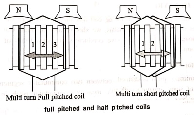
Coil Span
Coil span is defined as
the peripheral distance between two sides of a coil, measured in term of the
number of armature slots between them. That means, after placing one side of
the coil in a particular slot, after how many conjugative slots, the other side
of the same coil is placed on the armature. This number is known as coil span.
If the coil span is
equal to the pole pitch, then the armature winding is said to be full ‒pitched.
In this situation, two opposite sides of the coil lie under two opposite poles.
Hence emf induced in one side of the coil will be in 180° phase shift with emf
induced in the other side of the coil. Thus, the total terminal voltage of the
coil will be nothing but the direct arithmetic sum of these two emfs. If the
coil span is less than the pole pitch, then the winding is referred as
fractional pitched. In this coil, there will be a phase difference between
induced emf in two sides, less than 180°. Hence resultant terminal voltage of
the coil is vector sum of these two emf's and it is less than that of full‒pitched
coil.
In practice, coil pitch
(or Span) as low as eight tenth of a Pole Pitch, is employed without much
serious reduction in emf. Fractional pitched windings are purposely used to
effect substantial saving in copper of the end connection and for improving
commutation.
Pitch of Armature Winding
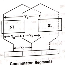
Back Pitch (YB)
A coil advances on the
back of the armature. This advancement is measured in terms of armature
conductors and is called back pitch. It is equal to the number difference of
the conductor connected to a given segment of the commutator.
Front Pitch (YF)
The number of armature
conductors or elements spanned by a coil on the front is called front pitch.
Alternatively, we define the front‒pitch as the distance between the second
conductor of the next coil which connects the front, i.e., commutator end of
the armature. In other words, it is the number difference of the conductors
connected together at the back end of the armature. We are showing both front
and back pitches for a lap, and a wave windings in the figure below.
Resultant Pitch (YR)
It is the distance
between the beginning of one coil and the beginning of the next coil to which
it is connected. As a matter of precautions, we should keep in mind that all
these pitches, though normally stated concerning armature conductors, are also
times of armature slots or commutator bars.
Commutator Pitch (YC)
Commutator pitch is
defined as the distance between two commutator segments which two ends of same
armature coil are connected. We measure commutator pitch in term of commutator
bars or segment.
Single Layer Armature Winding
We place armature coil
sides in the armature slots differently. In some arrangement, each one side of
an armature coil occupies a single slot. In other words, we place one coil side
in each armature slot. We refer this arrangement as single layer winding.
Two Layer Armature Winding
In other types of
armature winding, arrangement two coil sides occupy every armature slot; one
occupies upper half, and another one occupies the lower half of the slot. We so
place the coils in two layers winding that if one side occupies upper half,
then another side occupies the lower half of some other slot at a distance of
one coil pitch away.
Armature Winding of A DC Machine
Based on type of
winding connections we classified armature winding of a dc machine into two
types. These winding connections are same for DC generator & DC motor.
Types of Windings in DC Machine,
1. Lap winding
2. Wave winding
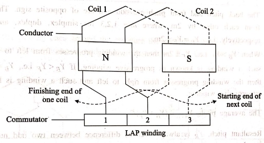
Lap winding of a DC Machine
In this type of winding
the completing end of one coil is connected to a commutator segment and to the
start end of adjacent coil located under the same pole and similarly all coils
are connected. This type of winding is known as lap because the sides of
successive coils overlap each other.
Lap winding may be
simplex (single) or multiplex (duplex or triplex) winding. In simplex lap
winding the connection of the winding is that there are as many parallel paths
as there are number of poles. Whereas for duplex, the number of parallel paths
are equal to. twice that of the number of poles and for triplex it is thrice.
For this reason, the lap winding is called multiple or parallel winding. The
sole purposes of such type of windings are,

(a) To increase the
number of parallel paths enabling the armature current to increase i.e., for
high current output.
(b) To improve
commutation as the current per conductor decreases.
Notes on Lap winding
1. The coil or back
pitch YB must be approximately equal to pole pitch i.e., YB = Z/P.
2. The back pitch and
front pitch are odd and are of opposite sign. They differ from each other by
2m, where m = 1,2,3 for simplex, duplex, and triplex respectively. i.e., YB=YF±2m.
When YB>YF
i.e., YF±2m then the winding progresses from left to right and such
a winding is known as progressive winding. If YB<YF
i.e., YB = YF‒2m then the winding progresses from right
to left and such a winding is known as retrogressive winding.
3. The average pitch, YAVE
= (YB+YF) / 2.
4. Resultant pitch, YR
is always even as difference between two odd numbers is even and is equal to
2m.
5. Commutator pitch, YC
= m i.e., 2, 3, 4 etc. for simplex, duplex, triplex, quadruplex etc.
6. Number of parallel
paths = mP. Where, m = multiplicity. Example: For instance, the number of
parallel paths for a 6‒pole duplex lap winding is given by 6×2 = 12 paths.
7. The total number of
poles are equal to the total number of brushes.
8. If Ia is
the total armature current, then current per parallel path is Ia/P.
9. Lap winding is used
for low voltage and high current machines.
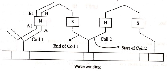
Wave winding of a DC Machine
In wave winding the
coils which are carrying current in one direction are connected in series
circuit and the carrying current in opposite direction are connected in another
series circuit. A wave winding is shown in figure.
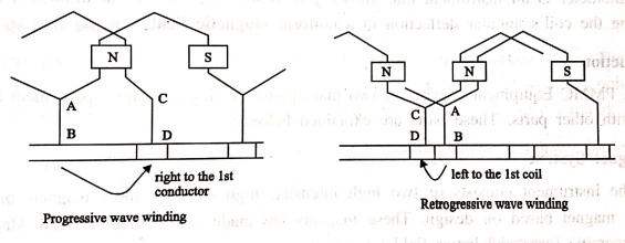
If after passing once
around the armature the winding falls in a slot to the left of its starting
point then winding is said to be retrogressive. If it fails one slot to the
right it is progressive.
Basic Electronics and Electrical Engineering: Practical Experimentation : Tag: Basic Engineering : - To Study the Construction and Working Principle of DC Machines
Basic Electronics and Electrical Engineering: Practical Experimentation
Under Subject

Basic Electronics and Electrical Engineering
EE25C04 1st Semester ECE Dept | 2025 Regulation | 2nd Semester 2025 Regulation
Related Subjects

English Essentials I
EN25C01 1st Semester | 2025 Regulation | 1st Semester 2025 Regulation

தமிழர் மரபு - Heritage of Tamils
UC25H01 1st Semester | 2025 Regulation | 1st Semester 2025 Regulation

Applied Calculus
MA25C01 Maths 1 M1 - 1st Semester | 2025 Regulation | 1st Semester 2025 Regulation

Applied Physics I
PH25C01 1st Semester | 2025 Regulation | 1st Semester 2025 Regulation

Applied Chemistry I
CY25C01 1st Semester | 2025 Regulation | 1st Semester 2025 Regulation

Makerspace
ME25C04 1st Semester | 2025 Regulation | 1st Semester 2025 Regulation

Computer Programming C
CS25C01 1st Semester | 2025 Regulation | 1st Semester 2025 Regulation

Computer Programming Python
CS25C02 1st Semester | 2025 Regulation | 1st Semester 2025 Regulation

Fundamentals of Electrical and Electronics Engineering
EE25C03 1st Semester | 2025 Regulation | 1st Semester 2025 Regulation

Introduction to Mechanical Engineering
ME25C03 1st Semester | 2025 Regulation | 1st Semester 2025 Regulation

Introduction to Civil Engineering
CE25C01 1st Semester Civil Department | 2025 Regulation | 1st Semester 2025 Regulation

Essentials of Computing
CS25C03 1st Semester - AID CSE IT Department | 2025 Regulation | 1st Semester 2025 Regulation

Applied Physics I Laboratory
PH25C01 1st Semester practical Laboratory Manual | 2025 Regulation | 1st Semester Laboratory 2025 Regulation

Applied Chemistry I Laboratory
CY25C01 1st Semester practical Laboratory Manual | 2025 Regulation | 1st Semester Laboratory 2025 Regulation

Computer Programming C Laboratory
CS25C01 1st Semester practical Laboratory Manual | 2025 Regulation | 1st Semester Laboratory 2025 Regulation

Computer Programming Python Laboratory
CS25C02 1st Semester practical Laboratory Manual | 2025 Regulation | 1st Semester Laboratory 2025 Regulation

Engineering Drawing
ME25C01 EEE Mech Dept | 2025 Regulation | 2nd Semester 2025 Regulation
Basic Electronics and Electrical Engineering
EE25C04 1st Semester ECE Dept | 2025 Regulation | 2nd Semester 2025 Regulation