Basic Electronics and Electrical Engineering: Practical Experimentation
To study the construction and working principle of PMMC and moving iron instrument
To study the construction and working principle of PMMC and moving iron instrument.
Construction
and working principle of PMMC and moving iron instrument
Aim
To study the
construction and working principle of PMMC and moving iron instrumen.
Apparatus
Meter Demonstration
ckt, Connecting Wire, D.C Power supply
Theory
PMMC
PMMC
A Permanent Magnet
Moving Coil (PMMC) meter - also known as a D'Arsonval meter or galvanometer is
an instrument that allows you to measure the current through a coil by
observing the coil's angular deflection in a uniform magnetic field.
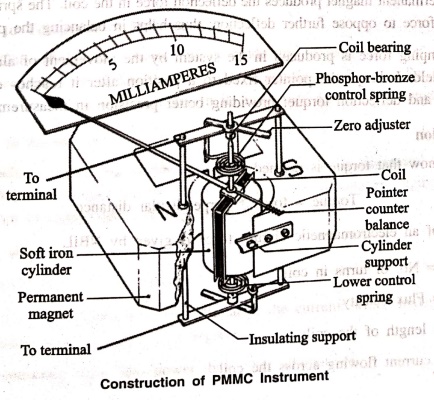
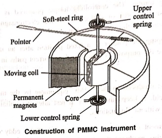
Construction
A PMMC Equipment
consists of two main parts; moving coil and a permanent magnet along with other
parts. These parts are explained below:
1. Magnet System
The instrument consists
of two high intensity, high coercive force magnets or a big U‒shape magnet
based on design. These magnets are made up of Alcomax and Alnico for higher
coercive force and better field intensity.
In many designs, an
additional soft iron cylinder is placed in between the magnetic poles to make
the field uniform; while reducing air reluctance to increasing field strength.
2. Moving Coil
It is one of the main
components of permanent magnet moving coil equipment; and is made up of copper
coils wounded to a rectangular block in between the magnetic poles. Made up of
Aluminium; the rectangular block is called Aluminium former pivoted to the
jewelled bearing. It is what allows the coil to rotate freely.
Non‒metallic former
like that of aluminium is used for current measurement; while metallic former
with high electromagnetic damping is used to measure voltage.
3. Control
Two spring made of
phosphorus bronze acts as a control system for the permanent magnet moving
coil. These springs are mounted on the jewel bearing of PMMC; providing the
essential controlling torque. The controlling torque produced is mainly due to
ribbon suspension. They oppose the force of deflection; so the electromagnetic
force (of Moving Coil) came in equilibrium with the spring tension.
This helps in keeping
the pointer at a fixed position after an initial deflection. These control
springs also serve the purpose of providing lead current paths in and out of the
system.
4. Damping System
Damping torque is
produced in the PMMC equipment by the movement of aluminium core in the
magnetic field. It keeps the pointer at rest after the initial deflection. This
helps in proper measurement without fluctuations.
Due to the movement of
the coil in the magnetic field; eddy current is produced in the aluminium
former. this produces the damping force / Torque which opposes the further
motion of the coil. Slowly the pointer deflection reduces and finally at a
fixed position.
5. Scale and Pointer
The pointer connected
to the moving coil moves moving coil moves over a marked scale. The pointer
moves along with the coil deflection to show readings marked on the scale. A
pointer is a simple construction with light weight design and twisted section
to reduce parallax error.
A Parallax error can be
further reduced by proper alignment of pointer blades to the initial scale.
Working Principle of a PMMC Instrument
When a current caring
conductor is placed in a magnetic field; it experiences a force perpendicular
to the field and the current (Fleming
Left Hand Rule). This force tends to move the conductor. According to
Fleming left‒hand rule; if your left‒hand thumb, fore finger, and middle finger
are at 90 degrees to each other. Then the magnetic field would be along with
the fore finger, current across the middle while the force along with the
thumb.
When current flows in
the coil on the aluminium former; a magnetic field is produced in the coil in
proportion to the current flow. This electromagnetic force along with a static
magnetic field from the permanent magnet produces the deflection force in the
coil. The spring then produces the controlling force to oppose further
deflection; thus helps in balancing the pointer.
Then damping force is
produced in the system by the movement of aluminium core in the magnetic field.
It keeps the pointer fixed to a position after it reaches equilibrium with the
controlling and deflection torque; providing better precision in measurement.
Torque Equation
As we know that torque
is defined as:
Torque = force *
perpendicular distance
In case of an
electromagnetic circuit, force is given by NBIL
where,
N = No. of turns in
coil;
B = Flux density;
L = length of the coil;
I = current flowing
across the coil
Therefore now torque
becomes T = NBIL * D
оr
T = NBI * A
or
T=G*I
A ‒ Area
G= NBA (constant)
As we know that
deflecting torque Td = controlling torque Tc
and
Tc=K*θ
GI= Kθ
This equation shows
that the deflection of a PMMC instrument is directly proportional to the
electric current flowing across the coil.
Error in PMMC Equipment
1. Error due to magnetism
Permanent magnet loses
their magnetism with time; this is called magnet aging. With plenty of heat and
vibration on the ship (especially Engine Room); There is a reduction of magnetism
due to accelerated aging. This decrease in magnetic strength reduce the coil deflection
affecting the readings.
2. Error due to Temperature Difference
Moving Coil of PMMC
instrument is made up of copper wires; the temperature coefficients of copper
wire is known to be 0.004 per degree Celsius. So with increase in temperature,
there will be a high increase in its resistance altering the actual reading.
3. Error due to Spring
Aging leads to
weakening of spring tension; this results in decreased deflection of the moving
coil. This error is opposite to that of the error due to magnetic aging and
sometimes cancel each other to reduce much difference in the final readings.
Advantages of PMMC Equipment
1. High weight to
torque ratio.
2. It has pointer
deflection proportional to the current; which makes the scale more uniform over
an arc of 270 degrees.
3. It consumes much
less power than other alternatives.
4. No hysteresis loss.
5. Unaffected by a
stray magnetic field; perfect equipment for on‒board applications.
6. All‒purpose
equipment; can be used as an ammeter, voltmeter, and galvanometer.
Disadvantages of PMMC Equipment
1. It only works for
Direct current (D.C).
2. It's costly than its
other alternatives.
3. It can show false
reading due to the above stated reasons (cause of errors in permanent magnet
moving coil instrument).
Moving Iron:
Moving Iron:
The instrument in
which the moving iron is used for measuring the flow of current or voltage is
known as the moving iron instrument.
It works on the
principle that the iron place near the magnet attracts towards it. The force of
attraction depends on the strength of the magnet field. The magnetic field
induces by the electromagnet whose strength depends on the magnitude of the
current passes through it.
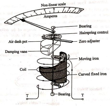
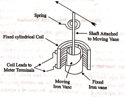
Construction and Working
In Moving Iron
Instruments, a plate or van of soft iron or of high permeability steel forms
the moving element of the system. The iron van is so situated that it can move
in the magnetic field produced by a stationary coil.
The stationary coil is
excited by the current or voltage under measurement. When the coil is excited,
it becomes an electromagnet and the iron van moves in direction of offering low
reluctance path. Thus the force of attraction is always produced in a direction
to increase the inductance of coil. Mind that as the van follows the low
reluctance path, the net flux in air gap will increase which means increased
flux linkage of coil and hence inductance of coil will increase. It shall also
be noticed that, the inductance of coil is variable and depends on the position
of iron van.
Classification
There are two types of
moving iron instrument, Attraction and Repulsion type.
1. Attraction Type
The instrument in which
the iron plate attracts from the weaker field towards the stronger field such
type of instrument is known as the attraction type instrument.
Construction of Attraction Type Instrument
The stationary coil of
the attraction type instrument is flat and has a narrow opening. The moving
element is the flat disc of the iron core. The current flow through the
stationary coil produced the magnetic field which attracts the iron coil. The
iron vane deflects from the low magnetic field to the high magnetic field, and
the strength of the deflection is directly proportional to the magnitude of the
current flow through it. In short, we can say that the iron coil attracts
towards in.
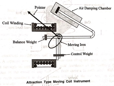
The attraction type
instruments use spring, which provided the controlling torque. The deflection
of the coil is reduced by the aluminium piston which is attached to the moving
coil.
2. Repulsion Type Instruments
The repulsion type
instrument has two vanes or iron plates. One is fixed, and the other one is
movable. The vanes become magnetised when the current passes through the
stationary coil and the force of repulsion occur between them. Because of a
repulsive force, the moving coil starts moving away from the fixed vane.
The spring provides the
controlling torque. The air friction induces the damping torque, which opposes
the movement of the coil. The repulsion type instrument is a non‒polarized
instrument, i.e., free from the direction of current passes through it. Thus,
it is used for both AC and DC.
Basic Electronics and Electrical Engineering: Practical Experimentation : Tag: Basic Engineering : - To study the construction and working principle of PMMC and moving iron instrument
Basic Electronics and Electrical Engineering: Practical Experimentation
Under Subject

Basic Electronics and Electrical Engineering
EE25C04 1st Semester ECE Dept | 2025 Regulation | 2nd Semester 2025 Regulation
Related Subjects

English Essentials I
EN25C01 1st Semester | 2025 Regulation | 1st Semester 2025 Regulation

தமிழர் மரபு - Heritage of Tamils
UC25H01 1st Semester | 2025 Regulation | 1st Semester 2025 Regulation

Applied Calculus
MA25C01 Maths 1 M1 - 1st Semester | 2025 Regulation | 1st Semester 2025 Regulation

Applied Physics I
PH25C01 1st Semester | 2025 Regulation | 1st Semester 2025 Regulation

Applied Chemistry I
CY25C01 1st Semester | 2025 Regulation | 1st Semester 2025 Regulation

Makerspace
ME25C04 1st Semester | 2025 Regulation | 1st Semester 2025 Regulation

Computer Programming C
CS25C01 1st Semester | 2025 Regulation | 1st Semester 2025 Regulation

Computer Programming Python
CS25C02 1st Semester | 2025 Regulation | 1st Semester 2025 Regulation

Fundamentals of Electrical and Electronics Engineering
EE25C03 1st Semester | 2025 Regulation | 1st Semester 2025 Regulation

Introduction to Mechanical Engineering
ME25C03 1st Semester | 2025 Regulation | 1st Semester 2025 Regulation

Introduction to Civil Engineering
CE25C01 1st Semester Civil Department | 2025 Regulation | 1st Semester 2025 Regulation

Essentials of Computing
CS25C03 1st Semester - AID CSE IT Department | 2025 Regulation | 1st Semester 2025 Regulation

Applied Physics I Laboratory
PH25C01 1st Semester practical Laboratory Manual | 2025 Regulation | 1st Semester Laboratory 2025 Regulation

Applied Chemistry I Laboratory
CY25C01 1st Semester practical Laboratory Manual | 2025 Regulation | 1st Semester Laboratory 2025 Regulation

Computer Programming C Laboratory
CS25C01 1st Semester practical Laboratory Manual | 2025 Regulation | 1st Semester Laboratory 2025 Regulation

Computer Programming Python Laboratory
CS25C02 1st Semester practical Laboratory Manual | 2025 Regulation | 1st Semester Laboratory 2025 Regulation

Engineering Drawing
ME25C01 EEE Mech Dept | 2025 Regulation | 2nd Semester 2025 Regulation
Basic Electronics and Electrical Engineering
EE25C04 1st Semester ECE Dept | 2025 Regulation | 2nd Semester 2025 Regulation