Applied Physics CSIE II: UNIT II: Logic Gates
Logic Gates
Symbol, Boolean expression, Truth Table, Circuit diagram
The different types of logic gates are: • AND Gate (•) • OR Gate (+) • NOT Gate (or) • XOR Gate • XNOR Gate • NAND Gate • NOR Gate. Let us discuss about all these gates.
LOGIC GATES
The
different types of logic gates are:
• AND Gate (•)
• OR Gate (+)
• NOT Gate (or)
• XOR Gate ( )
)
• XNOR Gate ( )
)
• NAND Gate
• NOR Gate
Let
us discuss about all these gates.
AND GATE (•)
The
AND gate gives an output of 1 only if both inputs are 1.
If
any input is 0, the output is 0.
For
an n‒input AND gate, the output is 1 only when all inputs are 1; otherwise, it
is 0.
The
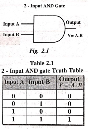
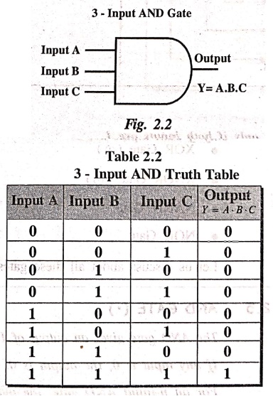
logic symbols of 2‒input AND gate and 3‒input AND gate are shown in Fig. 2.1
and Fig. 2.2, respectively.
Boolean expression
The
Boolean expression for an AND gate is written using a dot sign (•), which shows
a logical multiplication of inputs.
If
A and B are the inputs given to a 2‒input AND gate, than the output Y shall be
written as
Output Y= A • B
The
Truth Table for 2‒input AND gate and 3‒input AND gate are given in Table 2.1
and Table 2.2, respectively.
OR Gate (+)
The
OR gate is one of the most commonly used digital logic gates. Its output
becomes high (1) if any one of its inputs is high (1).
If
all the inputs are low (0), then the output will be low (0).
The
Boolean expression for an OR gate is written using a plus sign (+), which shows
the logical addition of inputs:
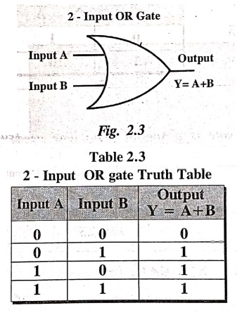
Output Y = A + B
For
A and B as inputs, the output Y will be high (true) when at least one of the
inputs is high (true).
The
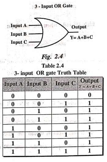
logic symbols of 2‒input OR gate & 3‒input OR gate are shown in Fig. 2.3
and Fig. 2.4, respectively.
The
Truth Table for 2‒input OR gate and 3‒input OR gate are given in Table 2.3 and
Table 2.4, respectively.
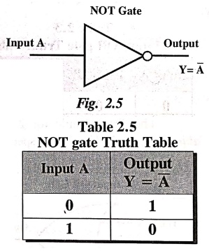
NOT Gate (INVERTER)
In
digital electronics, the NOT gate is a basic logic gate that has one input and
one output.
It
is also called as an inverter because it reverses the input state. i.e., the
output state is always the opposite of the input state.
If
the input is low (0), the output becomes high (1).
If
the input is high (1), the output becomes low (0).
The
Boolean expression of a NOT gate is written as:
Output Y = 
(or) Y = A'
The
logic symbol of NOT gate is shown in Fig. 2.5. The Truth Table of NOT gate is
shown in Table 2.5.
XOR GATE
()
In
digital electronics, the XOR gate is a special logic gate used to perform a
modulo‒2 sum. It is also known as the Exclusive OR (or) Ex‒OR gate.
The
symbol for XOR gate is ().
The
XOR gate recognise only words that have odd numbers of 1s (or) odd Parity
words.
The
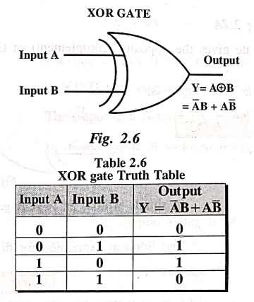
output of the XOR gate will be high (1) only when the two inputs are different.
This
means:
•
If one input is 0 and the other is 1, the output is 1.
•
If both inputs are the same (00 or 11), the output is 0.
If the two inputs are A and B, and the output
is Y, the Boolean expression shall be written as:

The
2‒input logic symbol for XOR gate is shown in Fig. 2.6 & its Truth Table is
given in Table 2.6.
Note:
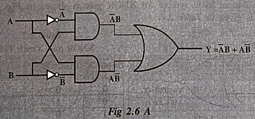
The XOR gate shall also be designed (or) built using OR, AND and NOT gates as
shown in Fig.2.6A.
XNOR GATE
()
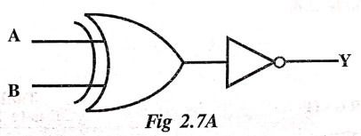
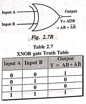
An
XOR gate followed by a NOT gate is called XNOR gate [Fig.2.7A].
i.e.,
XNOR gate recognizes even parity words.
The
output of an XNOR gate is high (1) when both inputs are the same (i.e., either
both are 1 or both are 0).
In
simple words, an XNOR gate gives the opposite (complement) of the XOR gate's
output.
The
Boolean expression for the XNOR gate is:
Output Y= A B
Here,
A and B are inputs, and Y is the output.
The
Boolean expression for XNOR gate shall also be written as:
Output Y AB + A' B' (or) AB + 
The
2‒input basic symbol for XNOR gate is shown in Fig. 2.7B & its Truth Table
is given in Table 2.7.
Note:
The XNOR gate is also called the Equivalence Gate.
NAND Gate (Not AND)
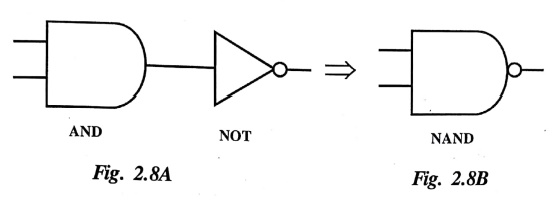
The
AND gate followed by a NOT gate is called NAND gate (Fig. 2.8A). It is formed
by connecting an AND gate and a NOT gate in series. The standard symbol for
NAND gate is shown in Fig. 2.8B.
The
NAND gate is also called as a Universal logic gate.
A
NAND gate can have two or more inputs and gives one output.
The
output of a NAND gate is high (1) unless all of its inputs are high (1).
In
simple words, it performs the opposite (inverted output) of an AND gate.
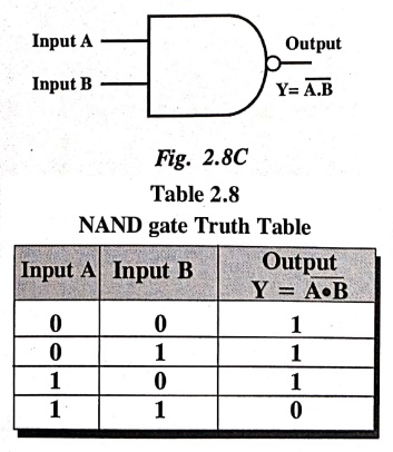
The
Boolean expression for a 2‒input NAND gate is:
Output Y = (A •B)' =

The
2‒input logic symbol for NAND gate is shown in Fig. 2.8C & its Truth Table
is given in Table 2.8.
NOR Gate (Not OR)
NOR Gate
The
term NOR is a constraction of NOT-OR and implies an OR function with complement
figure 4.8 (a) & (b) shows the standard symbol and equivalent circuit.
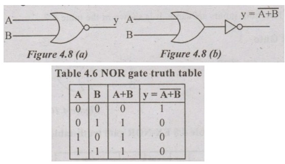
NOR
gate also universal gate, i.e NOR gate can be used to construct all basic gates
AND, OR and NOT gates. The truth table for a two input NOR gate is shown in
Table 4.6.
EX-OR
Gate
Ex-OR
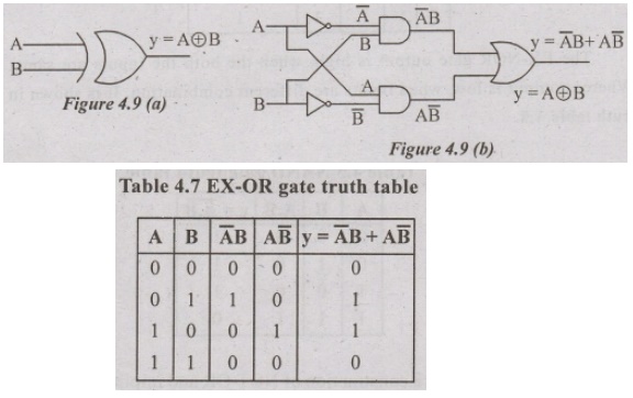
gate is an abbreviation of Exclusion-OR gate. An Ex-OR gate has two (or) more
inputs and one output. The standard and symbol and equivalent circuit is show
in figure 4.9 (a) & (b).
The
output EX-OR gate is logic high when the both inputs are different. When output
is low, both inputs are same. It is shown in the table 4.7.
EX-NOR
Gate
The
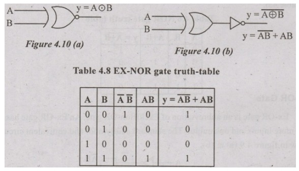
term EX-NOR gate is formed by NOT and exclusion OR gate. It is logical
equivalent circuit and symbol is shown in figure 4.10 (a) & (b).
The
EX-NOR gate output is high, when the both the inputs are same.Whereas output is
low, when inputs are different combination. It is shown in truth table 4.8.
Universal Gates
The
NAND and NOR gates are known as universal gates, since any logical function can
be implemented using NAND (or) NOR gates.
NAND Gates:
The
NAND gate can be constructed all the basic gates AND, OR and NOT.
NAND Gate as AND:
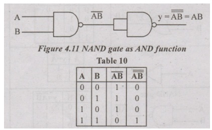
An
AND gate function can be generated using only NAND gates. It is generated by
simply inverting output of NAND gate AB = AB.
OR GATE using NAND
GATES
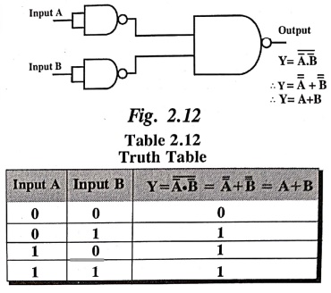
The
OR gate using only NAND gate is shown in Fig. 2.12 & its Truth
Table
is given in Table 2.12.
NOR GATE AS UNIVERSAL
GATE
Similar
to NAND gate, the NOR gate is also a universal gate. Let us discuss how a NOR
gate can be used to form all basic gates like AND, OR and NOT gates.
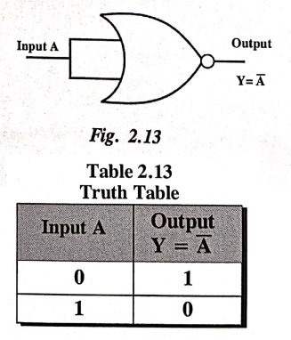
NOT GATE using NOR
GATES
A
NOT gate can be made by connecting all inputs of a NOR gate to single common
input.
The
NOT gate using only NOR gate is shown in Fig. 2.13 & its Truth Table is
given in Table 2.13.
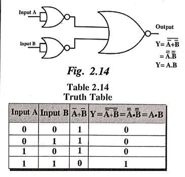
AND GATE USING NOR GATE
The
AND gate using only NOR gate is shown in Fig. 2.14 & its Truth
Table
is given in Table 2.14.
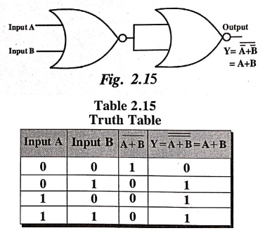
OR GATE USING NOR GATE
An
OR gate can be generated using NOR gate. It can be formed by inverting the
output of NOR gate.
The
OR gate using only NOR gate is shown in Fig. 2.15 & its Truth Table is
given in Table 2.15.
Applied Physics CSIE II: UNIT II: Logic Gates : Tag: Applied Physics : Symbol, Boolean expression, Truth Table, Circuit diagram - Logic Gates
Applied Physics CSIE II: UNIT II: Logic Gates
Under Subject

Applied Physics (CSIE) II
PH25C03 2nd Semester AIDS, CSE, IT, CSE(CY) Dept | 2025 Regulation | 2nd Semester 2025 Regulation
Related Subjects

English Essentials II
EN25C02 2nd Semester | 2025 Regulation | 2nd Semester 2025 Regulation

Tamils and Technology தமிழர்களும் தொழில்நுட்பமும்
UC25H02 2nd Semester | 2025 Regulation | 2nd Semester 2025 Regulation

Linear Algebra
MA25C02 2nd Semester | 2025 Regulation
Applied Physics (CSIE) II
PH25C03 2nd Semester AIDS, CSE, IT, CSE(CY) Dept | 2025 Regulation | 2nd Semester 2025 Regulation

Digital Principles and Computer Organization
CS25C06 2nd Semester AIDS, CSE, IT, CSE(CY) Dept | 2025 Regulation | 2nd Semester 2025 Regulation

Basic Electrical and Electronics Engineering
EE25C01 2nd Semester | 2025 Regulation | 2nd Semester 2025 Regulation

Python for Data Science
AD25201 2nd Semester AIDS Dept | 2025 Regulation | 2nd Semester 2025 Regulation

Re-Engineering for Innovation
ME25C05 2nd Semester | 2025 Regulation | 2nd Semester 2025 Regulation

Python for Data Science - Laboratory
AD25201 2nd Semester AIDS Dept | 2025 Regulation | 2nd Semester 2025 Regulation