Digital Principles and Computer Organization: Chapter 11: Memory
Error Detection and Correction in Computer Memory Systems
1. Parity Bit, 2. Hamming Code: Basic Concept, Finding the Parity Bits, Error Checking, General Formula, Bit Grouping Rule, 3. Single-Error Correction and Double-Error Detection (SECDED). Questions: 1. Explain the need for error detection and correction in digital communication and computer memory systems. 2. Describe how parity bits are used for error detection in data transmission. 3. Explain the principle of hamming code for single error correction with a neat example. 4. Construct the hamming (7,4) code for the data word 1011 and show the calculation of parity bits. 5. Describe the method of detecting and correcting a single-bit error using hamming code. 6. Explain how hamming code can be extended for double error detection. 7. List and explain the four possible cases of errors in Single Error Correction and Double Error Detection (SECDED) hamming code. 8. Write short notes on: a) Parity bit, b) Syndrome, c) Check bits in hamming code.
Error Detection and
Correction
•
When electrical signals interact in the data path of a memory unit, they can
sometimes cause errors during the storage or retrieval of binary data. To make
memory more reliable, error–detecting
and error–correcting codes are used.
•
The simplest error detection method is the parity
bit. A parity bit is an extra bit added to each data word before it is
stored in memory. When the data word is read back, its parity is checked.
•
If the parity is correct, the data is accepted.
•
If the parity is incorrect, it means an error has occurred.
However,
this method can only detect an error
– It cannot correct it.
•
To detect and correct errors, special codes called Error–Correcting Codes (ECC) are used. These codes generate several
check bits (Parity bits) and store
them along with the data. Each check bit represents the parity of a specific
group of data bits.
•
When the data is read from memory, new check bits are generated and compared
with the stored ones.
•
If they match, there is no error.
•
If they do not match, a unique pattern called a syndrome is produced. The syndrome indicates which specific bit is
incorrect. The system can then correct the
error by flipping (Complementing) that bit.
•
A single–bit error happens when one
bit changes from 1 to 0 or from 0 to 1 during reading or writing. Using ECC,
such single–bit errors can be detected and corrected automatically.
1. Parity Bit
•
A parity bit is used for the purpose of detecting errors during transmission of
binary information.
•
A parity bit is an extra bit included with a binary message to make the number
of 1s either odd or even.
•
The message, including the parity bit is transmitted and then checked at the
receiving end for errors. An error is detected if the checked parity does not
correspond with the one transmitted.
•
The circuit that generates the parity bit in the transmitter is called a parity generator and the circuit that
checks the parity in the receiver is called a parity checker.
•
In even parity the added parity bit will make the total number of 1s an even
amount. In odd parity the added parity bit will make the total number of 1s an
odd amount.
•
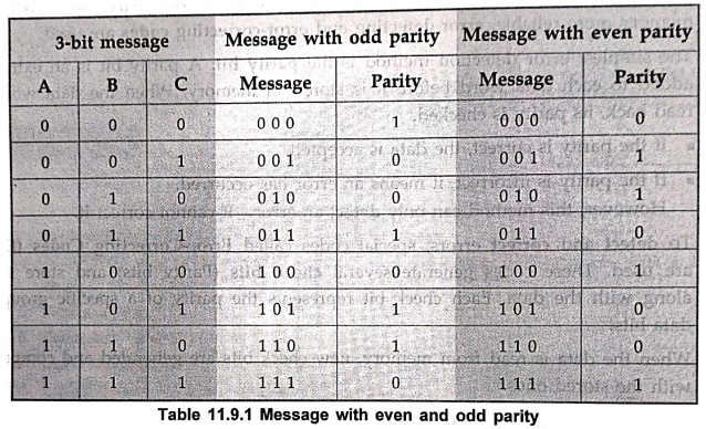
Table 11.9.1 shows the 3–bit message with even parity and odd parity.
Example: 1
Write a ASCII code for
the decimal digit 9 with an even parity. Place parity bit in the most
significant position.
Solution :
The
7–bit ASCII code for the decimal digit 9 is 0111001. This requires the addition
of a 0 in the most significant place to give even parity as shown.
Added
parity bit → 0 0 1 1 1 0 0 1
Example: 2
Write a ASCII code for
the alphabet 'A' with an odd parity. Place parity bit in the most significant
position.
Solution :
The
7–bit ASCII code for the alphabet 'A' is 1000001. This requires the addition of
a 1 in the most significant place to give odd parity, as shown.
.Added
parity bit → 1 1 0 0 0 0 0 1
•
At the receiving end, message with parity bit is received. Every time it time
it is checked for parity. When parity error is detected, receiver requests for
transmitter to re–transmit the message.
2. Hamming Code
•
One of the most popular error–correcting
codes used in computer memory (RAM) was developed by R. W. Hamming. The Hamming
code can both detect and correct
single–bit errors that occur while storing or reading data.
1. Basic Concept
•
In the Hamming code, some extra bits called parity bits (k) are added to the data bits (n). Thus, the total number of bits becomes n + k.
•
Each bit position in this combined word is numbered starting from 1. Positions
that are powers of 2 (1, 2, 4, 8, 16, ...) are used for parity bits, and the remaining
positions are used for data bits.
•
The code can be used for data words of any length.
Example :
Let us consider an 8–bit data word :
•
Data = 11000100
■
We need 4 parity bits (P1, P2, P4,
P8).
■
We arrange the 12 bits (8 data + 4
parity) as follows :

2. Finding the Parity Bits :
•
Each parity bit is chosen so that the total
number of 1s in certain positions (Including the parity bit itself) is even.
•
Using the exclusive–OR (XOR) operation, we calculated :
■
P1 = XOR of bits (3, 5, 7, 9, 11) = 1 ⊕
1 ⊕ 0 ⊕ 0 ⊕ 0 = 0
■
P2 = XOR of bits (3, 6, 7, 10, 11) = 1 ⊕
0
⊕ 0 ⊕ 1 ⊕ 0 = 0
■
P4 = XOR of bits (5, 6, 7, 12) = 1 ⊕
0 ⊕ 0 ⊕ 0 = 1
■
P8 = XOR of bits (9, 10, 11, 12) = 0 ⊕
1
⊕ 0 ⊕ 0 = 1
•
Thus, the complete 12–bit code word
stored in memory is : 0 0 1 1 1 0 0 1 0 1 0 0

3. Error Checking
•
When the word is read back from memory, the parity of each group is checked
again. The check bits are calculated
as :
C1
= XOR of bits (1, 3, 5, 7, 9, 11)
C2
= XOR of bits (2, 3, 6, 7, 10, 11)
C4
= XOR of bits (4, 5, 6, 7,12)
C8
= XOR of bits (8, 9, 10, 11, 12)
•
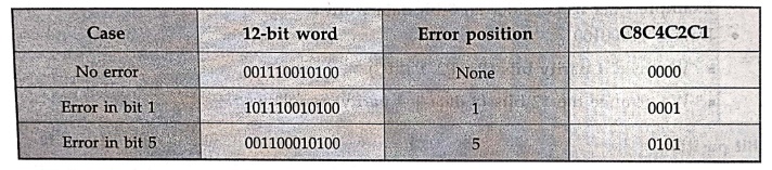
The check result is written as: C =
C8 C4 C2 C1
l■
If C = 0000, there is no error.
■
If C ≠ 0000, the binary value of C indicates the position of the bit in error.
• Example of error
detection
• If
an error is detected, it can be corrected
by simply complementing (Flipping)
the bit at the position given by C.
4. General Formula
• For
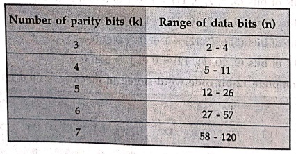
any hamming code with n data bits
and k parity bits, the following
relationship must hold :
2k
– 1 ≥ n + k
• This
ensures that there are enough parity bits to uniquely identify every bit
position. For example :
• Thus,
for 8 data bits, 4 parity bits are
required.
5. Bit Grouping Rule

• The
bit groups for each parity bit are determined from the binary representation of bit positions. Each parity bit checks all
positions where its corresponding binary digit is 1. For example :
■ P1 checks bits where the least
significant bit (LSB) = 1 = 1 → 1, 3, 5, 7, 9, 11 ...
■
P2 checks bits where the 2nd bit = 1
→ 2, 3, 6, 7, 10, 11 ...
■
P4 checks bits where the 3rd bit =
1→ 4, 5, 6, 7, 12 12...
■
P8 checks bits where the 4th bit = 1
→ 8, 9, 10, 11, 12 ...
Example: 3
A 12–bit Hamming code
word containing 8 bits of data and 4 parity bits is read from memory. What was
the original 8–bit data word that was written into memory if the 12–bit word
read out is as follows?
i) 000011101010
ii) 101110000110
iii)101111110100
Solution :
i) Code = 0 0 0 0 1 1 1
0 10 1 0

Now
calculate each check bit :
C1
= XOR(1, 3, 5, 7, 9, 11) = 0 ⊕ 0
⊕ 1 ⊕ 1 ⊕ 1 ⊕ 1 = 0
C2
= XOR(2, 3, 6, 7, 10, 11)= 0 ⊕ 0
⊕ 1 ⊕ 1 ⊕ 0 ⊕ 1 =1
C4
= XOR(4, 5, 6, 7, 12) = 0 ⊕1
⊕ 1 ⊕ 1 ⊕ 0 = 1
C8
= XOR(8, 9, 10, 11, 12) = 0 ⊕ 1
⊕ 0 ⊕ 1 ⊕ 0 = 0
Syndrome C8C4C2C1 = 0 1
1 0
= (binary 6) Error in bit 6
Correct code : 0
0 0 0 1 0 1 0 1 0 1 0
Correct data bits :
0 1 0 1 1 0 1 0
ii) Code = 1 0 1 1 1 0
0 0 0 1 1 0

Now
calculate each check bit :
C1 =
XOR(1, 3, 5, 7, 9, 11) = 1 ⊕ 1
⊕ 1 ⊕ 1 ⊕ 0 ⊕ 0 = 0
C2
= XOR(2, 3, 6, 7, 10, 11) = 0 ⊕ 1
⊕ 0 ⊕ 0 ⊕
1 ⊕ 1 = 1
C4
= XOR(4, 5, 6, 7, 12) = 1 ⊕
1 ⊕ 0 ⊕ 0 ⊕ 0 = 0
C8
= XOR(8, 9, 10, 11, 12) = 0 ⊕
0 ⊕ 1 ⊕ 1 ⊕ 0 = 0
Syndrome = C8C4C2C1 = 0
0 1 0 = (binary 2) Error in bit 2
Correct code :
1 1 1 1 1 0 0 0 0 0 1 1 0 Correct
data bits: 1 1 0 0 0 1 1 0
iii) Code = 1 0 1 1 1 1
1 1 0 1 0 0

Now
calculate each check bit :
C1 =
XOR(1, 3, 5, 7, 9, 11) = 1 ⊕ 1
⊕ 1 ⊕ 1 ⊕ 0 ⊕ 0 = 0
C2
= XOR(2, 3, 6, 7, 10, 11) = 0 ⊕ 1
⊕ 1 ⊕ 1 ⊕ 1 ⊕ 0 = 0
C4
= XOR(4, 5, 6, 7, 12) = 1 ⊕
1 ⊕ 1 ⊕ 1 ⊕ 0 = 0
C8
= XOR(8, 9, 10, 11, 12) = 1 ⊕ 0
⊕ 1 ⊕ 0 ⊕ 0 = 0
Syndrome = C8C4C2C1 =0 0 0 0 = No error
Original code :
1 0 1 1 1 1 1 1 0 1 0 0
Original data bits :
1 1 1 1 0 1 0 0
3. Single–Error Correction and Double–Error Detection (SECDED)
•
The basic Hamming code can detect and
correct only one error in a data word. However, by adding one extra parity bit, the code can also detect double errors. This improved version of the Hamming code is
called the Single–Error Correction and
Double–Error Detection (SECDED) code.
•
If we take the previous 12–bit Hamming code word, for example 001110010100, and
add an extra parity bit (P13) that covers
all 12 bits, we get a 13–bit code
word. The extra bit ensures that the total number of 1's in all 13 bits is even (Even parity).

•
When the 13–bit word is read from memory, two checks are made :
1. The Hamming check
bits (C8, C4, C2, C1) – Used to find if a single bit is in
error.
2. The overall parity
bit (P13) – Used to detect whether there are single
or multiple errors.
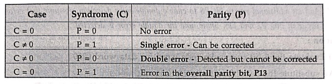
Based on these, four
possible cases can occur :
•
This method can sometimes detect more than two errors, though it is not guaranteed to find all multiple–bit
errors.
•
In practice, Integrated Circuits (ICs) often use a modified Hamming code for SECDED. This version uses an efficient parity configuration that
balances the XOR calculations for speed and hardware simplicity.
•
For example, IC 74637 is designed
for an 8–bit data word with a 5–bit check word, providing single–bit error correction and double–bit error detection. Similar ICs
are available for 16–bit and 32–bit data systems, and these are
commonly used with memory units to ensure reliable operation during both write and read processes.
Example: 4
Given the 8–bit data
word 01011011, generate the 13–bit composite word for the hamming code that
corrects single errors and detects double errors.
Solution :
Step 1:
Compute the 4 hamming parity bits
Using
the exclusive–OR (XOR) operation, we calculate:
■
P1 = XOR of bits (3, 5, 7, 9, 11) =
0 ⊕ 1 ⊕ 1 ⊕ 1 ⊕ 1 = 0
■
P2 = XOR of bits (3, 6, 7, 10, 11) =
0 ⊕ 0 ⊕ 1 ⊕ 0 ⊕ 1 = 0
■
P4 = XOR of bits (5, 6, 7, 12) = 1 ⊕ 0 ⊕ 1 ⊕ 1 = 1
■
P8 = XOR of bits (9, 10, 11, 12) = 1
⊕ 0 ⊕ 1⊕ 1 = 1
Thus,
the 12–bit code word stored in memory
is : 0 0 0 1 1 0 1 1 1 0 1 1

The overall parity bit,
P13
= 0 ⊕ 0 ⊕ 0 ⊕ 1 ⊕ 1 ⊕ 0 ⊕ 1 ⊕ 1 ⊕ 1 ⊕ 0 ⊕ 1 ⊕ 1
=
1
Thus, 13–bit SECDED
hamming code = 0 0 0 1 1 0 1 1 1 0 1 1 1
Example: 5
It is required to
formulate the hamming code for four data bits – D3, D5, D6, and D7 – along with
three parity bits – P1, P2, and P4.
a) Evaluate the 7–bit
composite code word for the data word 0010.
b) Determine the three
check bits (C4, C2, and C1), assuming no error has occurred.
c) Suppose an error
occurs in bit D5 during writing into memory. Show how this error is detected
and corrected.
d) Add an additional
parity bit P8 to enable double–error detection. Assume that errors occur in
bits P2 and D5. Show how the double error is detected.
Solution :
a) Evaluate the 7–bit
composite code word for data word 0010
We
substitute the data bits into their positions :

Now compute the parity bits :
• P1 covers bits 1, 3, 5, 7 → P1 = XOR(3,
5, 7) = XOR(0, 0, 0) = 0
•
P2 covers bits 2, 3, 6, 7 → P2 =
XOR(3, 6, 7) = XOR(0, 1, 0) = 1
•
P4 covers bits 4, 5, 6, 7 → P4 =
XOR(5, 6, 7) = XOR(0, 1, 0) = 1
Thus,
7–bit hamming code word = 0 1 0 1 0 1 0
b) Determine the check
bits (C1, C2, C4) assuming no error

Now
compute each check bit:
•
C1 = XOR(1, 3, 5, 7) = XOR(0, 0, 0,
0) = 0
• C2 = XOR(2, 3, 6, 7) = XOR(1, 0, 1, 0)
= 0
• C4 = XOR(4, 5, 6, 7) = XOR(1, 0, 1, 0)
= 0
error → Syndrome C =
000
c) Suppose an error
occurs in bit D5
Error
introduced : Bit 5 changes from 0 → 1

Now
recompute the check bits :
•
C1 = XOR(1, 3, 5, 7) = XOR(0, 0, 1, 0) = 1
•
C2 = XOR(2, 3, 6, 7) = XOR(1, 0, 1, 0) = 0
•
C4 = XOR(4, 5, 6, 7) = XOR(1, 1, 1, 0) = 1
Syndrome = C4C2C1 = 101 = 5th position
Error
is in bit 5 (D5)
Correct
it by flipping bit 5 → back to 0.
d) Add parity bit P8
for double–error detection
P8
= XOR(0, 1, 0, 1, 0, 1, 0) = 1
The
8–bit word is arranged as :

Now
assume errors occur in bits 2 and 5 →
new word becomes : 0 0 0 1 1 1 0 1
Compute
check bits again :
• C1 = XOR(1, 3, 5, 7) = XOR(0, 0, 1, 0)
= 1
•
C2 = XOR(2, 3, 6, 7) = XOR(0, 0, 1,
0) = 1
•
C4 = XOR(4, 5, 6, 7) = XOR(1, 1, 1,
0) = 1
•
Overall parity (P8) = XOR(all 7
bits) = 0 → Even parity
Now
:
C = (1,1,1) ≠ 000
P = 0 (No parity mismatch)
Hence
, syndrome ≠ 0 and parity bit correct → Indicates
a double–bit error (Uncorrectable but detectable).
Review Questions
1. Explain the need
for error detection and correction in digital communication and computer memory
systems.
2. Describe how parity
bits are used for error detection in data transmission.
3. Explain the
principle of hamming code for single error correction with a neat example.
4. Construct the
hamming (7,4) code for the data word 1011 and show the calculation of parity
bits. 5. Describe the method of detecting and correcting a single–bit error
using hamming code.
6. Explain how hamming
code can be extended for double error detection.
7. List and explain
the four possible cases of errors in Single Error Correction and Double Error
Detection (SECDED) hamming code.
8. Write short notes
on:
a) Parity bit,
b) Syndrome,
c) Check bits in
hamming code.
Digital Principles and Computer Organization: Chapter 11: Memory : Tag: : - Error Detection and Correction in Computer Memory Systems
Digital Principles and Computer Organization: Chapter 11: Memory
Under Subject

Digital Principles and Computer Organization
CS25C06 2nd Semester AIDS, CSE, IT, CSE(CY) Dept | 2025 Regulation | 2nd Semester 2025 Regulation
Related Subjects

English Essentials II
EN25C02 2nd Semester | 2025 Regulation | 2nd Semester 2025 Regulation

Tamils and Technology தமிழர்களும் தொழில்நுட்பமும்
UC25H02 2nd Semester | 2025 Regulation | 2nd Semester 2025 Regulation

Linear Algebra
MA25C02 2nd Semester | 2025 Regulation

Applied Physics (CSIE) II
PH25C03 2nd Semester AIDS, CSE, IT, CSE(CY) Dept | 2025 Regulation | 2nd Semester 2025 Regulation
Digital Principles and Computer Organization
CS25C06 2nd Semester AIDS, CSE, IT, CSE(CY) Dept | 2025 Regulation | 2nd Semester 2025 Regulation

Basic Electrical and Electronics Engineering
EE25C01 2nd Semester | 2025 Regulation | 2nd Semester 2025 Regulation

Python for Data Science
AD25201 2nd Semester AIDS Dept | 2025 Regulation | 2nd Semester 2025 Regulation

Re-Engineering for Innovation
ME25C05 2nd Semester | 2025 Regulation | 2nd Semester 2025 Regulation

Python for Data Science - Laboratory
AD25201 2nd Semester AIDS Dept | 2025 Regulation | 2nd Semester 2025 Regulation