Digital Principles and Computer Organization: Chapter 7: Sequential Circuits - Registers
Johnson or Twisting Ring or Switch Tail Counter
Questions: 1. Draw the 4-bit Johnson counter and explain the operation. 2. Design Johnson counter and state its advantages and disadvantages. 3. Design a 3 bit Johnson counter and explain its operation.
Johnson or Twisting
Ring or Switch Tail Counter
•
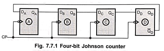
In a Johnson counter, the Q output of each stage of flip–flop is connected to
the D input of the next stage. The single exception is that the complement
output of the last flip–flop is connected back to the D–input of the first flip–flop
as shown in Fig. 7.7.1.
Note :
Johnson counter can be implemented with SR or JK flip–flops as well.
•
As shown in Fig. 7.7.1 there is a feedback from the rightmost flip–flop
complement output to the leftmost flip–flop input. This arrangement produces a
unique sequence of states.
•
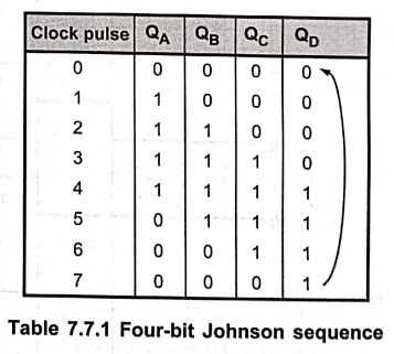
Initially, the register (all flip–flops) is cleared. So all the outputs, QA,
QB, QC, QD are zero. The output of last stage,
QD is zero. Therefore complement output of last stage,  D
is one. This is connected back to the D input of first stage. So DA
is one. The first falling clock edge produces QA = 1 and QB
= 0, QC = 0, QD = 0 since DB, DC, DD
are zero. The next clock pulse produces QA= 1,QB = 1, QC
= 0, QD = 0. The sequence of states is summarized in Table 7.7.1.
After 8 states the same sequence is repeated.
D
is one. This is connected back to the D input of first stage. So DA
is one. The first falling clock edge produces QA = 1 and QB
= 0, QC = 0, QD = 0 since DB, DC, DD
are zero. The next clock pulse produces QA= 1,QB = 1, QC
= 0, QD = 0. The sequence of states is summarized in Table 7.7.1.
After 8 states the same sequence is repeated.
•
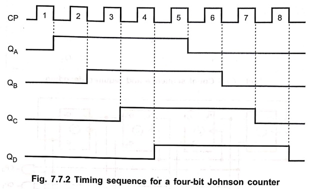
In this case, four–bit register is used. So the four–bit sequence has a total
of eight states. Fig. 7.7.2 gives the timing sequence for a four–bit Johnson
counter.
•
If we design a counter of five–bit sequence, it has a total of ten states, as
shown in Table 7.7.2.
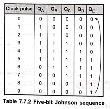
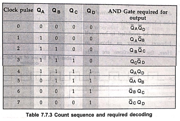
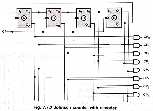
• So in general we can say that, an n–stage Johnson counter will produce a modulus of 2 × n, where n is the number of stages (i.e. flip–flops) in the counter. Thus, Johnson counter requires only half the number of flip–flops compared to the standard o ring counter. However, it requires more flip–flop than binary counter. As shown in tables, the counter will 'fill up' with 1s from left to right and then it will 'fill up' with 0s again. Another advantage of this type of sequence is that it is readily decoded with two input AND gates. Table 7.7.3 gives the count sequence and required decoding.
Example: 1
Design a 4–bit, 8–state
Johnson counter using IC 74X194. Show how same counter can be modified as self
correcting Johnson counter.
Solution :
Johnson
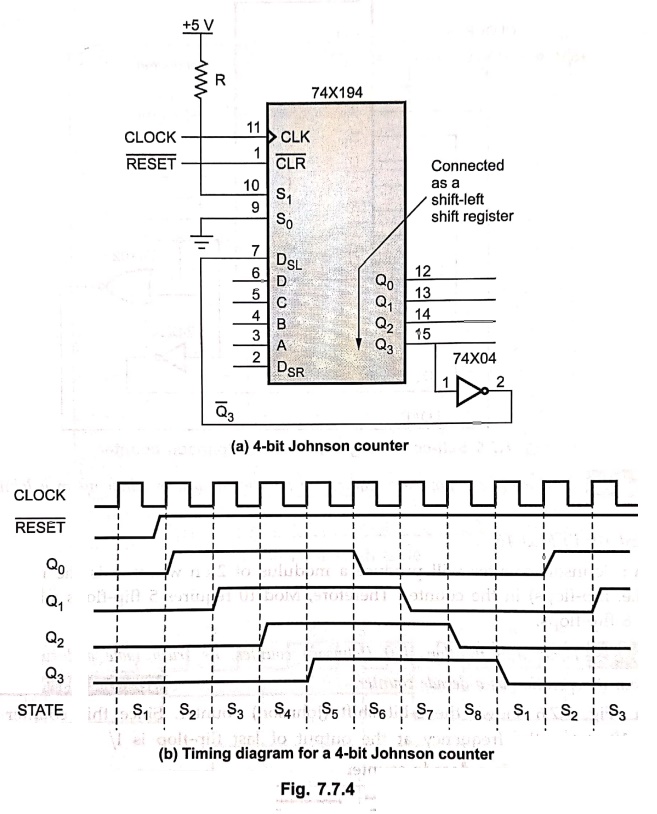
counter is basically a twisted ring counter. Fig. 7.7.4 (a) shows the basic
circuit for a Johnson counter and Fig. 7.7.4 (b) shows its timing diagram.
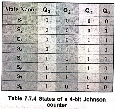
Table 7.7.4 shows the states of a 4–bit Johnson counter.
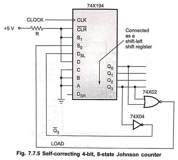
This
counter can be modified to have self correcting Johnson counter as shown in
Fig. 7.7.5. Here, the connections are made such that circuit loads 0001 as the
next state whenever the current state is 0XX0.
Example: 2
How many flip–flops are
required to implement each of following in a Johnson counter configuration:
i) Mod 10 ii) Mod 16
Solution :
Johnson
counter will produce a modulus of 2 × n where n is the number of stages (i.e.
flip–flops) in the counter. Therefore, Mod–10 requires 5 flip–flops and Mod–16
requires 8 flip–flops.
Example: 3
Draw a 5 flip–flop
shift (Johnson) counter, its truth table and waveforms. Explain its operation
as a decade counter.
Solution :
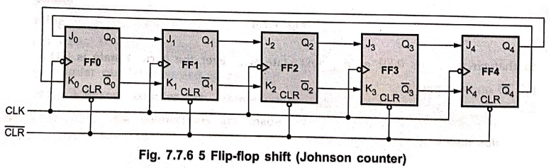
Fig.
7.7.6 shows the 5–bit shift (Johnson) counter. Since this counter goes through
10 states, the frequency at the output of last flip–flop is 1 / 10th
of the clock frequency and hence it is a decade counter.
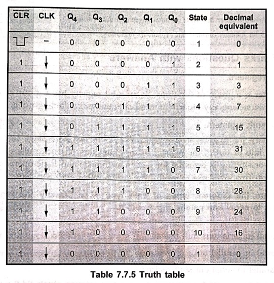
Table
7.7.5 shows the truth table for the 5 flip–flop shift counter and illustrates
its operation.
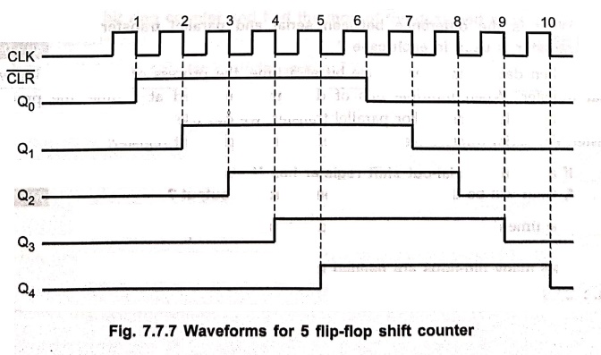
Waveform :
Review Questions
1. Draw the 4–bit
Johnson counter and explain the operation.
2. Design Johnson
counter and state its advantages and disadvantages.
3. Design a 3 bit
Johnson counter and explain its operation.
Digital Principles and Computer Organization: Chapter 7: Sequential Circuits - Registers : Tag: : - Johnson or Twisting Ring or Switch Tail Counter
Digital Principles and Computer Organization: Chapter 7: Sequential Circuits - Registers
Under Subject

Digital Principles and Computer Organization
CS25C06 2nd Semester AIDS, CSE, IT, CSE(CY) Dept | 2025 Regulation | 2nd Semester 2025 Regulation
Related Subjects

English Essentials II
EN25C02 2nd Semester | 2025 Regulation | 2nd Semester 2025 Regulation

Tamils and Technology தமிழர்களும் தொழில்நுட்பமும்
UC25H02 2nd Semester | 2025 Regulation | 2nd Semester 2025 Regulation

Linear Algebra
MA25C02 2nd Semester | 2025 Regulation

Applied Physics (CSIE) II
PH25C03 2nd Semester AIDS, CSE, IT, CSE(CY) Dept | 2025 Regulation | 2nd Semester 2025 Regulation
Digital Principles and Computer Organization
CS25C06 2nd Semester AIDS, CSE, IT, CSE(CY) Dept | 2025 Regulation | 2nd Semester 2025 Regulation

Basic Electrical and Electronics Engineering
EE25C01 2nd Semester | 2025 Regulation | 2nd Semester 2025 Regulation

Python for Data Science
AD25201 2nd Semester AIDS Dept | 2025 Regulation | 2nd Semester 2025 Regulation

Re-Engineering for Innovation
ME25C05 2nd Semester | 2025 Regulation | 2nd Semester 2025 Regulation

Python for Data Science - Laboratory
AD25201 2nd Semester AIDS Dept | 2025 Regulation | 2nd Semester 2025 Regulation