Digital Principles and Computer Organization: Chapter 7: Sequential Circuits - Registers
Sequential Circuits - Registers: Two Marks Important Questions and Answers
Digital Principles and Computer Organization
Digital Principles and Computer Organization: Chapter 7: Sequential Circuits - Registers: Anna University Part A Two Marks Important Questions and Answers
Digital Principles and Computer Organization:
Chapter 7: Sequential Circuits – Registers
Two Marks Questions
with Answers
1. Define
registers.
Answer: A register is a group
of flip–flops. So an n–bit register has a group of n flip–flops and is capable
of storing any binary information / number containing n–bits.
2. Define
shift registers.
Answer: The binary information
in a register can be moved from stage to stage within the register or into or
out of the register upon application of clock pulses. This type of bit movement
or shifting is essential for certain arithmetic and logic operations used in
microprocessors. This gives rise to group of registers called shift registers.
3. What
are the different types of shift type? or Classify the registers with respect
to serial and parallel input output.
Answer:
There
are five types. They are :
•
Serial in serial out shift register
•
Serial in parallel out shift register
•
Parallel in serial out shift register
•
Parallel in parallel out shift register
•
Bidirectional shift register
4. What
is the difference between serial and parallel transfer? What type of register
is used in each case?
Answer: When data is
transferred one bit at a time, the process of transfer is known as serial
transfer. When multiple bits of data are transferred at a time, the process is
known as parallel transfer. For parallel transfer, we can use parallel in and
parallel out register. For serial transfer we can use left shift or right shift
register.
5. If a
serial–in–serial–out shift register has N stages and if the clock frequency is f,
what will be time delay between input and output?
Answer: The time delay between
input and output is TD = N / f
6. How
many flip–flops are needed to build an 8 bit shift register?
Answer: 21 ≥ 8 n
= 3
7. What
is parallel shifting ?
Answer: In a shift register
all the data are moved simultaneously and then the technique is called parallel
shifting.
8. Define
universal shift register.
Answer: The register which has
both shifts (right–shift and left–shift) and parallel load capabilities is
referred to as universal shift register.
9. What
are the applications of a shift register?
Answer:
1.
Delay line
2.
Serial to parallel converter
3.
Parallel to serial converter.
4.
Pseudo–random binary sequence generator.
5.
Sequence detector.
10. Draw
the timing diagram of 4–bit ring counter.
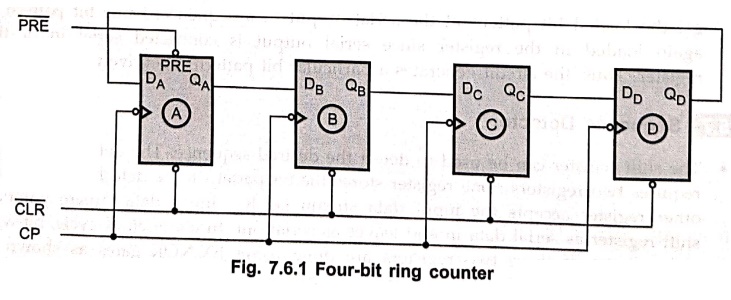
11. What
is a ring counter?
Fig.
7.6.1 shows the logic diagram for four–bit ring counter. As shown in the bale
Fig. 7.6.1, the Q output of each stage is connected to the D input of the next
stage and the output of last stage is fed back to the input of first stage. The  followed by
  makes the output of first stage to '1' and remaining outputs are zero, i.e. QA is one and QB, QC,QD are zero.
The
ring counter can be used for counting the number of pulses. The number of
pulses counted is read by noting which flip–flop is in state 1. No decoding
circuitry is required. Since there is one pulse at the output for each of the N
clock pulses, this circuit is also referred to as a divide–by–N–counter or an N
: 1 scalar. Ring counters can be instructed for any desired MOD number, that is
MOD–N ring counter requires N flip–flops.
12. What
are the uses of a ring counter?
Answer:
i)
Control section of a digital system.
ii)
Controlling events, which occur in strict time sequence.
13. What
is a cycle counter ?
Answer: A cycle counter is a
counter that outputs a stated number of counts and then stops.
14. Draw
a 2–bit ripple counter and convert this into a 2–bit ring counter.
15. Design a 3 bit ring counter and find the mod of the designed counter.
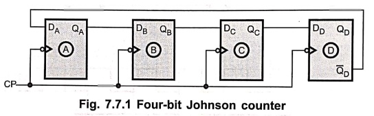
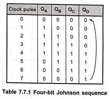
16. What is Johnson counter?
In
a Johnson counter, the Q output of each stage of flip–flop is connected to the
D input of the next stage. The single exception is that the complement output
of the last flip–flop is connected back to the D–input of the first flip–flop
as shown in Fig. 7.7.1.
Digital Principles and Computer Organization: Chapter 7: Sequential Circuits - Registers : Tag: : Digital Principles and Computer Organization - Sequential Circuits - Registers: Two Marks Important Questions and Answers
Digital Principles and Computer Organization: Chapter 7: Sequential Circuits - Registers
Under Subject

Digital Principles and Computer Organization
CS25C06 2nd Semester AIDS, CSE, IT, CSE(CY) Dept | 2025 Regulation | 2nd Semester 2025 Regulation
Related Subjects

English Essentials II
EN25C02 2nd Semester | 2025 Regulation | 2nd Semester 2025 Regulation

Tamils and Technology தமிழர்களும் தொழில்நுட்பமும்
UC25H02 2nd Semester | 2025 Regulation | 2nd Semester 2025 Regulation

Linear Algebra
MA25C02 2nd Semester | 2025 Regulation

Applied Physics (CSIE) II
PH25C03 2nd Semester AIDS, CSE, IT, CSE(CY) Dept | 2025 Regulation | 2nd Semester 2025 Regulation
Digital Principles and Computer Organization
CS25C06 2nd Semester AIDS, CSE, IT, CSE(CY) Dept | 2025 Regulation | 2nd Semester 2025 Regulation

Basic Electrical and Electronics Engineering
EE25C01 2nd Semester | 2025 Regulation | 2nd Semester 2025 Regulation

Python for Data Science
AD25201 2nd Semester AIDS Dept | 2025 Regulation | 2nd Semester 2025 Regulation

Re-Engineering for Innovation
ME25C05 2nd Semester | 2025 Regulation | 2nd Semester 2025 Regulation

Python for Data Science - Laboratory
AD25201 2nd Semester AIDS Dept | 2025 Regulation | 2nd Semester 2025 Regulation