Digital Principles and Computer Organization: Chapter 5: Sequential Circuits - Flip-Flops
Realization of One Flip-Flop using Other Flip-Flop
1. SR Flip-Flop to D Flip-Flop, 2. SR Flip-Flop to JK Flip-Flop, 3. SR Flip-Flop to T Flip-Flop, 4. JK Flip-Flop to T Flip-Flop, 5. JK Flip-Flop to D Flip-Flop, 6. D Flip-Flop to T Flip-Flop, 7. T Flip-Flop to D Flip-Flop, 8. JK Flip-Flop to SR Flip-Flop, 9. D Flip-Flop to SR Flip-Flop, 10. T Flip-Flop to SR Flip-Flop, 11. D Flip-Flop to JK Flip-Flop
Realization of One Flip–Flop
using Other Flip–Flop
•
It is possible to convert one flip–flop into another flip–flop with some
additional gates or simply doing some extra connection. Let us see few
conversions among flip–flops.
1. SR Flip–Flop to D Flip–Flop
•
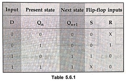
The excitation table for above conversion is as shown in Table 5.6.1.
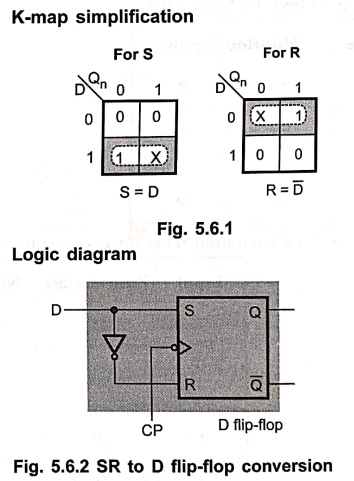
K–map simplification
& Logic diagram
2. SR Flip–Flop to JK Flip–Flop
•
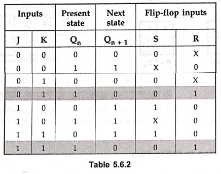
The excitation table for above conversion is as shown in Table 5.6.2.
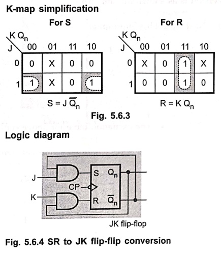
K–map simplification
& Logic diagram
3. SR Flip–Flop to T Flip–Flop
•
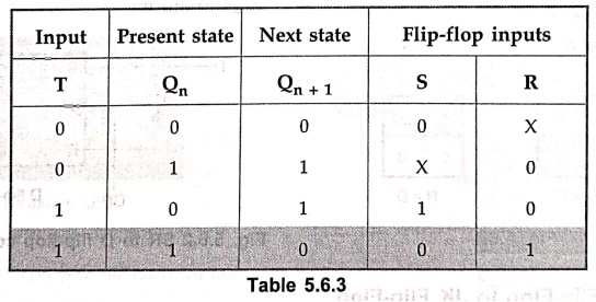
The excitation table for above conversion is as shown in Table 5.6.3.
K–map simplification
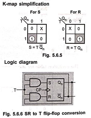
& Logic diagram
•
If we apply clock pulses to the circuit, the circuit output will toggle from 0
to 1 and 1 to 0. Thus, we can build 1–bit counter using SR flip–flop by
converting it to T flip–flop.
Example: 1
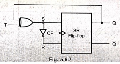
Prepare the truth table
for the circuit of Fig. 5.6.7 and show that it acts as a T–type flip–flop.
Solution :
For
SR flip–flop,
Qn+
1 = S+  Qn
Qn
= S+ SQn  )
)
= S (1+Qn) = S
We
have,
S = Qn ⊕ T
Qn+
1 = Qn ⊕
T
=T n +
n +  Qn
Qn
Characteristic equation of T flip–flop.
Looking
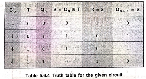
at column 1 and column 5 of Table 5.6.4 we can conclude that when T = 0, the
output does not change and when T = 1, the output toggles. Thus, the given
circuit acts as a T flip–flop. This is another way of implementing T flip–flop
using SR flip–flop.
4. JK Flip–Flop to T Flip–Flop
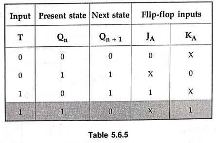
The
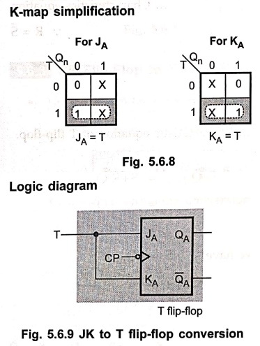
excitation table for above conversion is as shown in Table 5.6.5.
Logic diagram & K–map simplification
5. JK Flip–Flop to D Flip–Flop
•
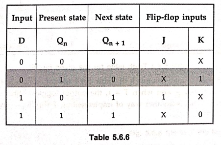
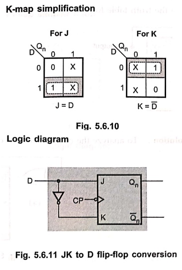
The excitation table for above conversion is as shown in Table 5.6.6.
K–map simplification & Logic diagram
6. D Flip–Flop to T Flip–Flop
•
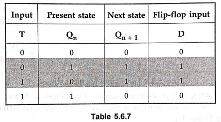
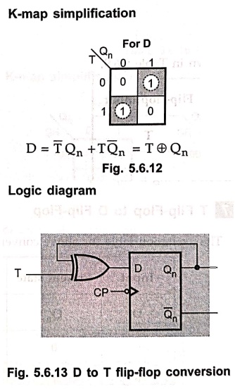
The excitation table for above conversion is as shown in Table 5.6.7.
K–map simplification & Logic diagram
Example: 2
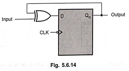
Analyze the circuit and
prove that it is equivalent to T flip–flop.
Solution :
To
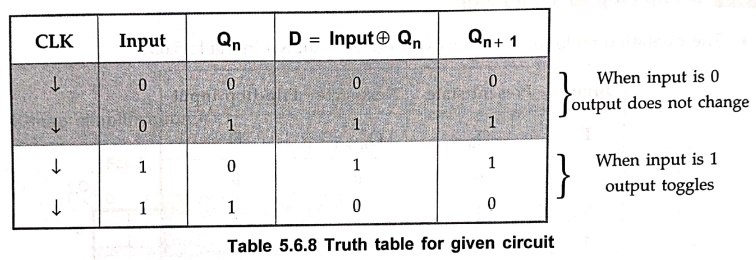
analyze the circuit means to derive the truth table for it.
We
have, D = Input ⊕ Qn
In
the above circuit, output does not change when input is 0 and it toggles when
input is 1. This is the characteristics of T flip–flop. Hence, the given
circuit is T flip–flop constructed using D flip–flop.
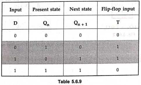
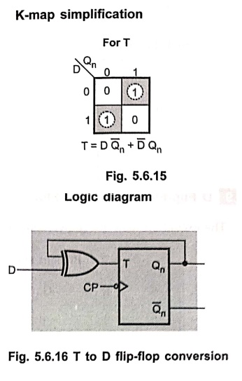
7. T Flip–Flop to D Flip–Flop
•
The excitation table for above conversion is as shown in Table 5.6.9.
K–map simplification & Logic diagram
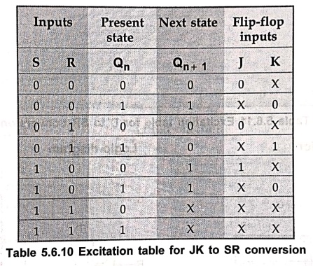
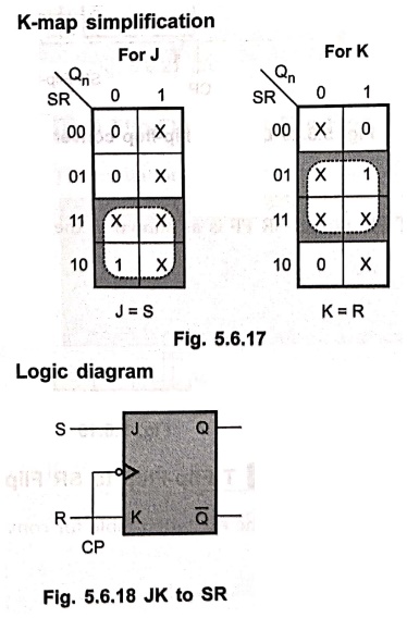
8. JK Flip–Flop to SR Flip–Flop
The
excitation table for above conversion is as shown in Table 5.6.10.
K–map simplification & Logic diagram
9. D Flip–Flop to SR Flip–Flop
•
The excitation table for above conversion is as shown in Table 5.6.11.
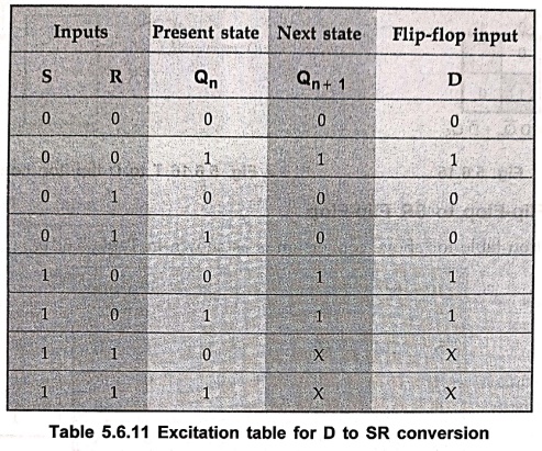
K–map simplification & Logic diagram
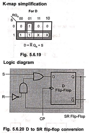
10. T Flip–Flop to SR Flip–Flop
•
The excitation table for conversion of T FF into an SR FF is as shown in the
table.
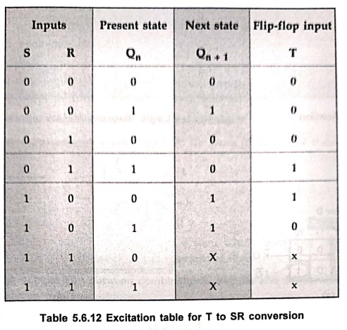
K–map simplification & Logic diagram
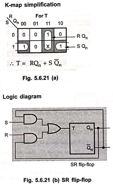
11. D Flip–Flop to JK Flip–Flop
•
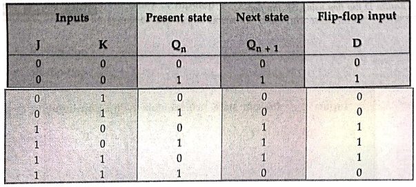
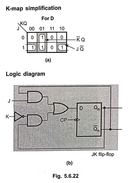
The excitation table for conversion of D flip–flop to JK flip–flop:
K–map simplification & Logic diagram
Review Questions
1. Convert JK flip–flop
to D flip–flop.
2. Convert D flip–flop
into T flip–flop.
3. Convert JK flip–flop
to T flip–flop.
4. Convert a SR flip–flop
into a D flip–flop.
5. Convert a T–FF into
an S–R FF. Draw the circuit.
6. How will you
convert a D flip–flop into JK flip–flop ?
7. Convert SR flip–flop
into JK flip–flop.
8. Convert SR flip–flop
into T flip–flop.
9. Convert T flip–flop
into D flip–flop.
10. Convert JK flip–flop
into SR flip–flop.
11. Convert D flip–flop
into SR flip–flop.
12. Realize D flip
flop using SR flip flop.
Digital Principles and Computer Organization: Chapter 5: Sequential Circuits - Flip-Flops : Tag: : - Realization of One Flip-Flop using Other Flip-Flop
Digital Principles and Computer Organization: Chapter 5: Sequential Circuits - Flip-Flops
Under Subject

Digital Principles and Computer Organization
CS25C06 2nd Semester AIDS, CSE, IT, CSE(CY) Dept | 2025 Regulation | 2nd Semester 2025 Regulation
Related Subjects

English Essentials II
EN25C02 2nd Semester | 2025 Regulation | 2nd Semester 2025 Regulation

Tamils and Technology தமிழர்களும் தொழில்நுட்பமும்
UC25H02 2nd Semester | 2025 Regulation | 2nd Semester 2025 Regulation

Linear Algebra
MA25C02 2nd Semester | 2025 Regulation

Applied Physics (CSIE) II
PH25C03 2nd Semester AIDS, CSE, IT, CSE(CY) Dept | 2025 Regulation | 2nd Semester 2025 Regulation
Digital Principles and Computer Organization
CS25C06 2nd Semester AIDS, CSE, IT, CSE(CY) Dept | 2025 Regulation | 2nd Semester 2025 Regulation

Basic Electrical and Electronics Engineering
EE25C01 2nd Semester | 2025 Regulation | 2nd Semester 2025 Regulation

Python for Data Science
AD25201 2nd Semester AIDS Dept | 2025 Regulation | 2nd Semester 2025 Regulation

Re-Engineering for Innovation
ME25C05 2nd Semester | 2025 Regulation | 2nd Semester 2025 Regulation

Python for Data Science - Laboratory
AD25201 2nd Semester AIDS Dept | 2025 Regulation | 2nd Semester 2025 Regulation