Digital Principles and Computer Organization: Chapter 12: IO Systems
DMA (Direct Memory Access)
Operation, Block Diagram, Uses, Data Transfer Modes
1. DMA Operation, 2. Comparison of I/O Program Controlled Transfer and DMA Transfer , 3. DMA Block Diagram, 4. Data Transfer Modes, 5. Use of DMA in a Computer System. Questions: 1. State the advantages of DMA over the other modes of I/O transfer. 2. What is DMA operation? State its advantages. 3. Why do we need DMA ? 4. Write note on: DMA 5. Explain in detail about Direct Memory Access methods (DMA). 6. Discuss the DMA driven data transfer technique. 7. Comparison between I/O program controlled transfer and DMA transfer. 8. With a neat sketch explain the working principle of DMA. 9. Explain the DMA. 10. What are the necessary operations needed to start an I/O operation using DMA? 11. Explain how DMA transfer is accomplished with a neat diagram. 12. Explain the steps involved in the DMA operation. 13. Discuss direct memory access in detail. 14. What is meant by Direct Memory Access? Explain the use of DMA controllers in a computer system. 15. Draw the typical block diagram of a DMA controller and explain how it is used for direct data transfer between memory and peripherals ? 16. Explain about DMA controller, with the help of a block diagram.
DMA (Direct Memory
Access)
•
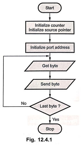
In software control data transfer, processor executes a series of instructions
to carry out data transfer. For each instruction execution fetch, decode and
execute phases are required. Fig. 12.4.1 gives the flowchart to transfer data
from memory to I/O device.
•
Thus to carry out these tasks processor requires considerable time. So this
method of data transfer is not suitable for large data transfers such as data
transfer from magnetic disk or optical disk to memory.
Drawbacks in programmed I/O and interrupt driven I/O
1.
The I/O transfer rate is limited by the speed with which the CPU can test and
service a device.
2.
The time that the CPU spends testing I/O device status and executing a number
of instructions for I/O data transfers can often be better spent on other
processing tasks.
•
To overcome above drawbacks an alternative technique, hardware controlled data
transfer can be used.
1. DMA Operation
•
DMA controlled data transfer is used for large data transfer. For example to
read bulk amount data from disk to main memory.
•
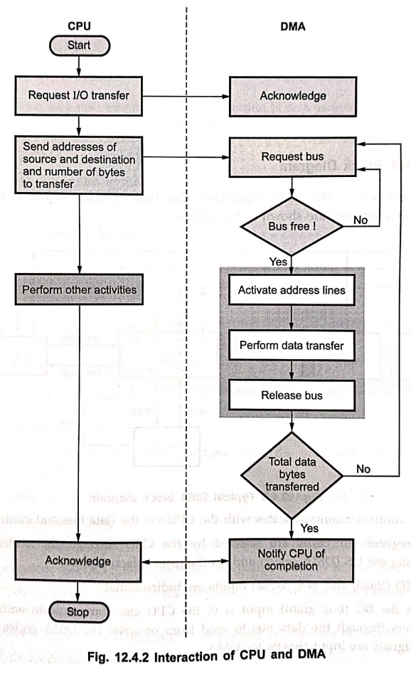
To read a block of data from the disk processor sends a series of commands to
the disk controller device telling it to search and read the desired block of
data from the disk.
•
When disk controller is ready to transfer first byte of data from disk, it
sends DMA request DRQ signal to the DMA controller.
•
Then DMA controller sends a hold request HRQ, signal to the processor HOLD
input. The processor responds this HOLD signal by floating its buses and
sending out a hold acknowledge signal HLDA, to the DMA controller.
•
When the DMA controller receives the HLDA signal, it takes the control of
system bus.
•
When DMA controller gets control of the buses, it sends the memory address
where the first byte of data from the disk is to be written. It also sends a
DMA acknowledge, DACK signal to the disk controller device telling it to get
ready to output the byte.
•
Finally, it asserts both the I/O read and memory write signals on the control
bus. Asserting the I/O read signal enables the disk controller to output the
byte of data from the disk on the data bus and asserting the memory write
signal enables the addressed memory to accept data from the data bus. In this
technique data is transferred directly from the disk controller to the memory
location without passing through the processor or the DMA controller.
•
Thus, the CPU is involved only at the beginning and end of the transfer.
•
After completion of data transfer, the HOLD signal is deasserted to give
control of all buses back to the processor.
Fig.
12.4.2 shows the interaction between processor and DMA discussed above.
2. Comparison of I/O Program Controlled Transfer and DMA Transfer
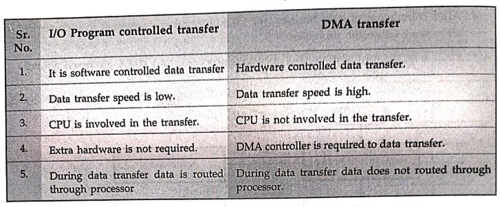
I/O Program controlled transfer
1.
It is software controlled data transfer
2.
Data transfer speed is low.
3.
CPU is involved in the transfer.
4.
Extra hardware is not required.
5.
During data transfer data is routed through processor.
DMA transfer
1.
Hardware controlled data transfer.
2.
Data transfer speed is high.
3.
CPU is not involved in the transfer.
4.
DMA controller is required to data transfer.
5.
During data transfer data does not routed through processor.
3. DMA Block Diagram
•
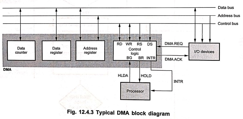
For performing the DMA operation, the basic blocks required in a DMA
channel/controller are shown in Fig. 12.4.3.
•
DMA controller communicates with the CPU via the data bus and control lines.
•
The registers in DMA are selected by the CPU through the address bus by
enabling the DS (DMA select) and RS (Register select) inputs.
•
The RD (Read) and WR (write) inputs are bidirectional.
•
When the BG (bus grant) input is 0, the CPU can communicate with the DMA
registers through the data bus to read from or write the DMA registers RD and
WR signals are input signals for DMA.
•
When BG = 1, the CPU has relinquished the buses and the DMA can communicate
directly with the memory by specifying an address in the address bus and
activating the RD or WR signals (RD and WR are now output signals for DMA). DMA
consists of data count, data register, address register and control logic.
•
Data counter register stores the number which gives the number data transfers
to be done in one DMA cycle. It is automatically decremented after each word
transfer.
•
Data register acts as buffer whereas address register initially holds the
starting address of the device. Actually, it stores the address of the next
word to be transferred. It is automatically incremented or decremented after
each word transfer.
•
After each transfer, data counter is tested for zero. When the data count
reaches zero, the DMA transfer halts.
•
The DMA controller is normally provided with an interrupts capability, in which
case it sends an interrupt to processor to signal the end of the I/O data
transfer.
4. Data Transfer Modes
•
DMA controller transfers data in one of the following three modes :
■
Single transfer mode (cycle stealing)
■
Block transfer mode
■
Demand or burst transfer mode
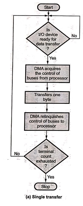
Single transfer mode (Cycle stealing mode)
In
this mode device can make only one transfer (byte or word). After each transfer
DMAC gives the control of all buses to the processor. Due to this processor can
have access to the buses on a regular basis.
It
allows the DMAC to time share the buses with the processor, hence this mode is
most commonly used.
The
operation of the DMA in a single transfer mode is as given below :
1.
I/O device asserts DRQ line when it is ready to transfer data.
2.
The DMAC asserts HLDA line to request use of the buses from the processor.
3.
The processor asserts HLDA, granting the control of buses to the DMAC.
4.
The DMAC asserts  to the requesting I/O device and
executes DMA bus cycle, resulting data transfer.
to the requesting I/O device and
executes DMA bus cycle, resulting data transfer.
5.
I/O device deasserts its DRQ after data transfer of one byte or word.
6.
DMA deasserts line.
7.
The word/byte transfer count is decremented and the memory address is incremented.
8.
The HOLD line is deasserted to give control of all buses back to the processor.
9.
HOLD signal is reasserted to request the use of buses when I/O device is ready
to transfer another byte or word. The same process is then repeated until the
last transfer.
10.
When the transfer count is exhausted, terminal count is generated to indicate
the end of the transfer.
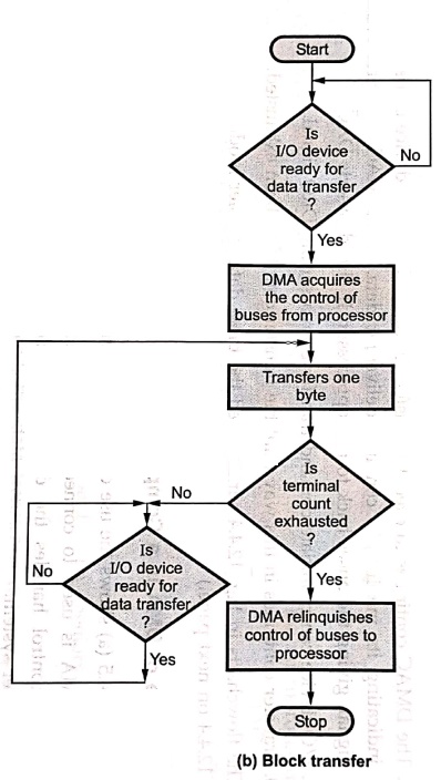
Block transfer mode
In
this mode device can make number of transfers as programmed in the word count
register. After each transfer word count is decremented by 1 and the address is
decremented or incremented by 1. The DMA transfer is continued until the word
count "rolls over" from zero to FFFFH, a Terminal Count (TC) or an
external END of Process ( ) is encountered. Block transfer mode is
used when the DMAC needs to transfer a block of data.
) is encountered. Block transfer mode is
used when the DMAC needs to transfer a block of data.
The
operation of DMA in block transfer mode is as given below :
1.
I/O device asserts DRQ line when it is ready to transfer data.
2.
The DMAC asserts HLDA line to request use of the buses from the microprocessor.
3.
The microprocessor asserts HLDA, granting the control of buses to the DMAC.
4.
The DMAC asserts to the requesting I/O device and executes
DMA bus cycle, resulting data transfer.
5.
I/O device deasserts its DRQ after data transfer of one byte or word.
6.
DMA deasserts line.
7.
The word/byte transfer count is decremented and the memory address is incremented.
8.
When the transfer count is exhausted, the data transfer is not complete and the
DMAC waits for another DMA request from the I/O device, indicating that it has
another byte or word to transfer. When DMAC receives DMA request steps through
are repeated.
9.
If the transfer count is not exhausted, the data transfer is complete then DMAC
deasserts the HOLD to tell the microprocessor that it no longer needs the
buses.
10.
Microprocessor then deasserts the HLDA signal to tell the DMAC that it has
resumed control of the buses.
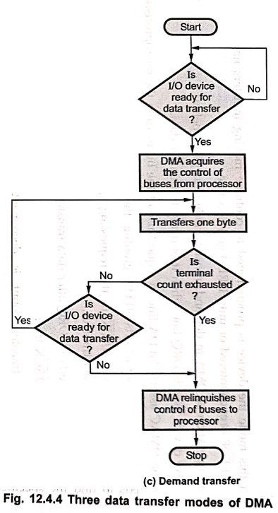
Demand transfer mode
In
this mode the device is programmed to continue making transfers until a TC or
external is encountered or until DREQ goes inactive.
The
operation of DMA in demand transfer mode is as given below :
1.
I/O device asserts DRQ line when it is ready to transfer data.
2.
The DMAC asserts HLDA line to request use of the buses from the microprocessor.
3.
The microprocessor asserts HLDA, granting the control of buses to the DMAC.
4.
The DMAC asserts to the requesting I/O device and executes
DMA bus cycle, resulting data transfer.
5.
I/O device deasserts its DRQ after data transfer of one byte or word.
6.
DMA deasserts line.
7.
The word/byte transfer count is decremented and the memory address is
incremented.
8.
The DMAC continues to execute transfer cycles until the I/O device deasserts
DRQ indicating its inability to continue delivering data. The DMAC deasserts
HOLD signal, giving the buses back to microprocessor. It also deasserts .
9.
I/O device can re–initiate demand transfer by reasserting DRQ signal.
10.
Transfer continues in this way until the transfer count has been exhausted.
The
flowcharts in Fig. 12.4.4 summarized the three data transfer modes of DMA.
5. Use of DMA in a Computer System
•
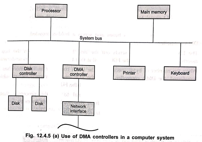
Fig. 12.4.5 (a) shows the use of DMA in a computer system.
•
The DMA is used to connect a high–speed network to the computer bus. The DMA
control handles the data transfer between high–speed network and the computer
system.
•
It is also used to transfer data between processor and floppy disk with the
help of floppy disk controller.
•
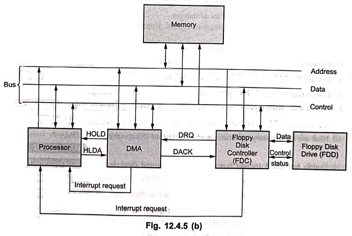
Let us see how DMA controller does the data transfer between floppy disk and
the processor. The Fig. 8.10.5 (b) shows the interface required for such
transfer.
•
The sequence of events that takes place during the data transfer are as follows
:
•
When processor needs some data from the disk, it sends a series of command
words to registers inside the floppy disk controller.
•
The floppy disk controller then proceeds to find the specified track and sector
on the disk.
•
In the mean while processor loads the DMA data counter and address register.
The data counter is loaded with count equal to the number of bytes to be
transferred to or from the memory. The address register is loaded with the
starting address of the memory.
•
When the controller reads the first byte of data from a sector, it sends DMA
request, DRQ signal to the DMA controller. DMA request sends a hold request
signal to the HOLD input of the processor.
•
The processor then floats its buses and sends a hold–acknowledge signal to the
DMA controller.
•
The DMA controller then sends out the first transfer address on the bus and
asserts the input of the FDC to tell it that the DMA transfer is underway.
•
When the number of bytes specified in the DMA controller initialization has
been transferred, the DMA controller asserts the (end of process)
signal, which is connected to the TC (Terminal Count) input of the FDC.
•
This causes FDC to generate interrupt signal to tell the processor that the
requested block of data has been read from disk to a buffer in memory.
•
Similar process is required to write data into the disk.
Review Questions
1. State the
advantages of DMA over the other modes of I/O transfer.
2. What is DMA
operation? State its advantages.
3. Why do we need DMA
?
4. Write note on : DMA
5. Explain in detail
about Direct Memory Access methods (DMA).
6. Discuss the DMA
driven data transfer technique.
7. Comparison between
I/O program controlled transfer and DMA transfer.
8. With a neat sketch
explain the working principle of DMA.
9. Explain the DMA.
10. What are the
necessary operations needed to start an I/O operation using DMA?
11. Explain how DMA
transfer is accomplished with a neat diagram.
12. Explain the steps
involved in the DMA operation.
13. Discuss direct
memory access in detail.
14. What is meant by
Direct Memory Access? Explain the use of DMA controllers in a computer system.
15. Draw the typical
block diagram of a DMA controller and explain how it is used for direct data
transfer between memory and peripherals ?
16. Explain about DMA
controller, with the help of a block diagram.
Digital Principles and Computer Organization: Chapter 12: IO Systems : Tag: : Operation, Block Diagram, Uses, Data Transfer Modes - DMA (Direct Memory Access)
Digital Principles and Computer Organization: Chapter 12: IO Systems
Under Subject

Digital Principles and Computer Organization
CS25C06 2nd Semester AIDS, CSE, IT, CSE(CY) Dept | 2025 Regulation | 2nd Semester 2025 Regulation
Related Subjects

English Essentials II
EN25C02 2nd Semester | 2025 Regulation | 2nd Semester 2025 Regulation

Tamils and Technology தமிழர்களும் தொழில்நுட்பமும்
UC25H02 2nd Semester | 2025 Regulation | 2nd Semester 2025 Regulation

Linear Algebra
MA25C02 2nd Semester | 2025 Regulation

Applied Physics (CSIE) II
PH25C03 2nd Semester AIDS, CSE, IT, CSE(CY) Dept | 2025 Regulation | 2nd Semester 2025 Regulation
Digital Principles and Computer Organization
CS25C06 2nd Semester AIDS, CSE, IT, CSE(CY) Dept | 2025 Regulation | 2nd Semester 2025 Regulation

Basic Electrical and Electronics Engineering
EE25C01 2nd Semester | 2025 Regulation | 2nd Semester 2025 Regulation

Python for Data Science
AD25201 2nd Semester AIDS Dept | 2025 Regulation | 2nd Semester 2025 Regulation

Re-Engineering for Innovation
ME25C05 2nd Semester | 2025 Regulation | 2nd Semester 2025 Regulation

Python for Data Science - Laboratory
AD25201 2nd Semester AIDS Dept | 2025 Regulation | 2nd Semester 2025 Regulation