Digital Principles and Computer Organization: Chapter 12: IO Systems
I/O Devices and Interface Standards
1. PCI (Peripheral Component Interconnect): Features, PCI Configurations, PCI Bus Signals, Data Transfer, 2. USB: USB Features, USB System, USB Connector, USB Data Encoding Format, USB Commands, USB Packet Format, Data Transfer Types, 3. SATA. Questions: 1. Write short note on advantages of USB over older I/O bus architectures. 2. Write notes on : USB. 3. Explain the protocols of USB. 4. Discuss the salient features of the USB operation. 5. What are the advantages of USB interface ? 6. Write a short note on SATA. 7. List the features of SATA.
I/O Devices and
Interface Standards
•
Input/Output (I/O) devices are hardware components that allow a computer system
to interact with the external world. These devices can be broadly classified
got into three categories:
1. Input
Devices – Used to enter data into the computer.
Examples :
Keyboard, mouse, scanner, microphone, sensors.
2. Output
Devices – Present processed
information to the user.
Examples :
Monitor, printer, speakers, actuators.
3. Storage
and Communication Devices –
Provide permanent storage or data exchange between systems.
Examples :
Hard Disk Drives (HDDs), Solid State Drives (SSDs), network adapters, external
drives.
•
Each device communicates with the CPU through an interface, which defines how data is transferred, controlled and
synchronized between the device and the computer.
•
To ensure compatibility and efficient data transfer, I/O devices follow
standardized interfaces. These standards specify electrical connections, signaling methods, data transfer protocols, and
command sets.
1. PCI (Peripheral Component Interconnect)
•
In early 1992, Intel formed an another industrial group in relation to be PC
bus. The main intension behind the formation of group was to overcome the weaknesses
in the ISA and EISA buses. They designed PCI (Peripheral Component Interface)
specifications in June 1992, and updated in April 1993.
1. Features
1.
It is designed to economically meet the I/O requirements of modern systems. It
requires very few chips to implement and support other buses attached to the
PCI bus.
2.
It bypasses the standard I/O bus, uses the system bus to increase the bus clock
speed and take full advantage of the CPU's data path.
3.
It has an ability to function with a 64–bit data bus,
4.
It has high bandwidth. The information is transferred across the PCI bus at 33
MHz, at the full data width of the CPU. When the bus is used in conjunction
with a 32–bit CPU, the bandwidth is 132 Mbytes/sec. It is calculated as follows
:
33
MHz × 32–bit = 1,056 Mbits/sec
1,056
Mbits/sec + 8 = 132 Mbytes/sec
5.
PCI bus is designed to support a variety of microprocessor based configurations
including both single and multiprocessor systems.
6.
The PCI bus can operate concurrently with the processor bus. The CPU can be
processing data in a external cache while the PCI bus is busy transferring
information between other parts of the system.
7.
The PCI bus is processor – independent bus that can function as a mezzanine or
peripheral bus.
8.
It makes use of synchronous timings and centralized arbitration scheme.
9.
It delivers better system performance for high – speed I/O subsystems (e.g.
graphic display adapters, network interface controllers, disk controllers and
so on).
10.
The PCI interface contains a 256 bytes configuration memory which allows the
computer to interrogate the PCI interface. This feature allows the system to automatically
configure itself for the PCI plug–board and hence it is referred to as plug–and–play.
2. PCI Configurations
•
As mentioned earlier, PCI bus is designed to support single processor as well
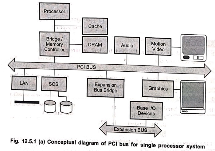
as multiprocessor systems. Fig. 12.5.1 (a) shows a typical use of PCI in a
single processor system.
•
Notice that the processor bus is separate and independent of the PCI bus. The
processor connects to the PCI bus through an integrated circuit called a PCI
bridge. The memory controller and PCI bridge provides tight coupling with the processor
and delivers data at high speeds.
Fig.
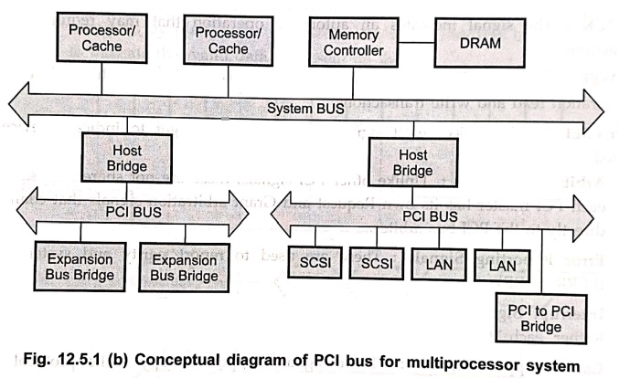
12.5.1 (b) shows a typical use of PCI in a multiprocessor system. As shown in
Fig. 12.5.1 in multiprocessor systems one or more PCI configurations may be
connected by bridges to the processor's system bus. Again, the use of bridges
keeps the PCI independent of the processor speed yet provides the ability to
receive and deliver data rapidly.
3. PCI Bus Signals
PCI signals are
functionally divided into the following groups :
• System
Signals : System signals include clock and reset signals
(Test clock, clock, Test Reset, Reset).
• Address
and Data Signals : Address and data signals include 64
lines that are time– multiplexed for addresses and data lines (AD0 – AD63). The
other signals from this group such as parity, command and byte enable signals
are used to interpret and validate the signal lines that carry the addresses
and data (PAR, C/BE).
•
Interface Control Signals : Interface control signals control
the timing of transactions and provide co–ordination among initiators and
targets. These are as follows :
 FRAME :
The current master uses this signal to indicate the start and duration of a
transaction. The signal is asserted at the start and deasserted when the
initiator is ready to begin the final data phase.
FRAME :
The current master uses this signal to indicate the start and duration of a
transaction. The signal is asserted at the start and deasserted when the
initiator is ready to begin the final data phase.
 IRDY :
The current master (initiator) uses this signal to indicate that it is ready to
read or write valid data.
IRDY :
The current master (initiator) uses this signal to indicate that it is ready to
read or write valid data.
 TRDY:
The target device (selected device) uses this signal to indicate that it is
ready to read or write valid data.
TRDY:
The target device (selected device) uses this signal to indicate that it is
ready to read or write valid data.
 STOP :
This signal indicates that the current target wishes the initiator to stop the current
transaction.
STOP :
This signal indicates that the current target wishes the initiator to stop the current
transaction.
 LOCK :
The signal indicates an automatic operation that may require multiple transactions.
LOCK :
The signal indicates an automatic operation that may require multiple transactions.
IDSEL :
This initialization device select signal is used as a chip select during
configuration read and write transactions.
 DEVSEL :
This device select signal is used by the target to indicate device has
selected.
DEVSEL :
This device select signal is used by the target to indicate device has
selected.
•
Arbitration Signals : Unlike other PCI signals, these are not
shared lines. Rather, each PCI master has its own Request and Grant arbitration
signals that connect it directly to the PCI bus arbiter.
• Error
Reporting Signals : These are used to report parity and
system errors ( ,
, ).
).
•
Interrupt Signals : Like bus arbitration signals these are
not shared signals. Rather, each PCI device has its own interrupt signals  .
.
• Cache
Support Signals : These signals support snoopy cache
protocol ( , SDONE).
•
JTAG/Boundary Scan Signals : These signals support
testing procedures defined in IEEE standard 149.1 (TCK – Test clock, TDI – Test
Input, TDO– Test Output, TMS Test Mode Select, TRST – Test Reset).
4. Data Transfer
Every
data transfer on the PCI bus is a single transaction consisting of one address
phase and one or more data phases. Let us see the typical read cycle to read 32–bit
word from memory on the PCI bus. All the events during read cycle are
synchronized with the falling edge of the clock cycle. The devices connected to
the bus sample the bus lines on the rising edge at the beginning of a bus
cycle. The events during the bus cycle are explained below and they are also
labeled on the diagram.
1.
The master asserts signal to indicate the start of a
transaction. This signal remains asserted until initiator is ready to begin the
data phase. The initiator puts the start address on the address bus, and
initiates read cycle by activating  lines.
2.
At the beginning of clock2, the target device recognizes its address on the
address bus.
3.
The initiator ceases the address lines and it changes the information on the lines to designate which address lines are to be used for transfer for the
currently addressed data from 1 to from 1 to 4 bytes. The initiator also
asserts IRDY to indicate that it is ready for the first data byte.
4.
The selected target asserts to indicate that it has
recognized its address BA and it responds by placing the requested data on the
address bus. It then asserts to indicate that valid data is
present on the bus.
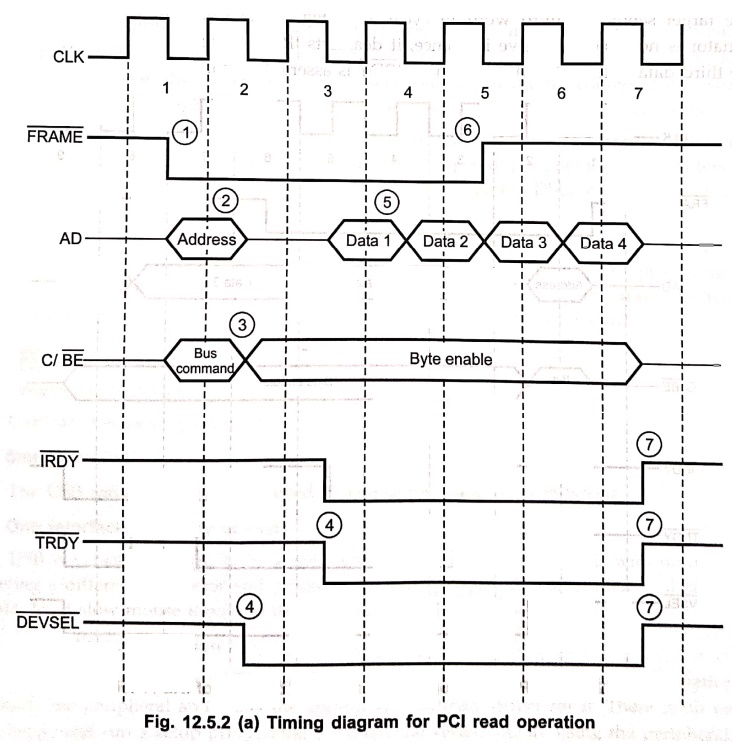
5.
The initiator reads the data at the beginning of clock 4 and changes the byte
enable lines as needed in preparation for the next read.
6.
The initiator deasserts signal indicating that it is
second last data byte Laud transfer.
7.
The initiator deasserts and the target deasserts and , bus to the idle state.
Similar
kind of handshaking signals are activated during PCI write operation. Here, the
data from initiator is copied into the targeted devices.
Fig.
12.5.2 (b) shows how the and signals can be
used by the initiator and target, respectively to pause the data transfer in
the middle of a transaction. As shown in Fig. 12.5.2 (b) the read cycle
operation is same upto two data bytes transfer. The target sends the third word
in cycle 5. In Fig. 12.5.2 (b), it is assumed that the initiator is not able to
receive it. Hence, it deasserts . In response, the target
holds the third data byte on the AD lines until is
asserted again.
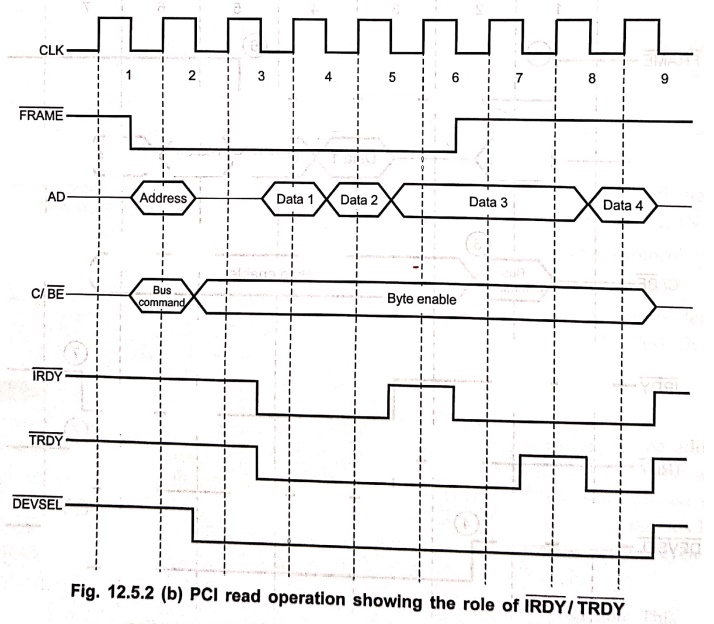
In
cycle 6, it is assumed that the initiator is ready to receive next data bytes
thus is asserts signal and reads third data byte. At
this point, it is assumed that the target is not ready to transfer the fourth
word. The target informs this by deasserting line. In cycle
8, target sends the fourth word and asserts . Since signal is deasserted during the third data byte transfer, the transaction
ends after the fourth data byte transfer.
2. USB
•
USB gives fast and flexible interface for connecting all kinds of peripherals.
•
USB is playing a key role in fast
growing consumer areas like digital imaging, PC telephony, and multimedia
games, etc.
•
The presence of USB in most new PCs and its plug–n–play capability, means that
PCs and peripherals (such as CD ROM drives, tape and floppy drives, scanners,
printers, video devices, digital cameras, digital speakers, telephones, modems,
key boards, mice, digital joysticks and others) will automatically configure
and work together, with high degree of reliability, in this exciting new
application areas.
•
USB opens the door to new levels of innovation and its use for input devices.
There are also brand new opportunities of all types of peripherals from
printers to scanners to high speed connection such as Ethernet, DSL, cable and
satellite communications.
•
USB has advantages that specifically benefit developers, including the hardware
designers who select components and design the circuits, the PC programmers who
write the software that communicates with USB peripherals, and peripherals all
programmers who write the code that resides inside USB peripherals.
1. USB Features
1. Simple connectivity
USB
offers simple connectivity.
2. Simple cables
The
USB cable connector are keyed so you cannot plug them in wrong.
3. One interface for
many device
USB
is versatile enough to be usable with many kinds of peripherals with no need of
having a different connector and protocols for each peripheral. USB supports
all kinds of data, from slow mouse inputs to digitized audio and compresses
video.
4. Automatic
configuration
When
a user connects a USB peripheral to a powered system, windows automatically
detects the peripheral and loads the appropriate software driver for it. There
is no need to locate and run a setup programme or restart the system before
using the peripheral.
5. No user setting
USB
peripherals do not have uses selectable setting such as port address and interrupt
request (IRQ) lines.
6. Frees hardware
resources for other devices
Using
USB for as many peripherals as possible frees up IRQ lines for the peripherals
that do require them.
7. Hot pluggable (Plug–and
play)
You
can install or remove a peripheral regardless of the power state.
8. Data transfer rates
USB
supports three data transfer rates, 480 Mb/s (high–speed), 12 Mb/s (full–speed)
and 1.5 Mb/s (low–speed)
9. Coexistence with
IEEE 1394
USB
2.0 and IEEE 1394 offer similar data rate primarily differ in terms of
application focus.
10. Reliability
Reliability
of USB results from both the hardware design and data transfer protocols.
11. Low cost
Even
though USB is more complex than earlier interfaces, its components, and cables
are inexpensive. A device with a USB interface is likely to cost the same or
less than its equivalent older interfaces.
12. Low power
consumption
Power
circuits and code automatically power down USB peripherals when not in use, yet
keep them ready to respond when needed.
13. Flexibility
USB's
four transfer type and three speed make it feasible for many type of
peripherals.
14. Operating system
support
Windows
98 was the first Windows operating system to reliably support USB, and its
successors such as Windows 2000 support USB as well. Other computers and
operating systems also have USB support. ON apple's iMac, the only peripherals
connectors are USB. Other Macintoshes also support USB, and support is in
progress for Linux, NetBSD, and FreeBSD.
2. USB System
•
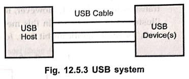
Fig. 12.5.3 shows the basic components of USB system. It consists of USB host,
USB device and USB cable. The USB host is a personal computer (PC) and gion
devices are scanner, printer etc. There will be only one host in the USB
system, however there can be 127 devices in the USB system.
3. USB Connector
•
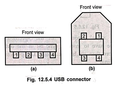
Fig. 12.5.4 shows the pin–out of the USB connector.
•
There are two types of USB connectors.
•
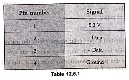
In either case, there are four signals as indicated in Table 12.5.1 The 5.0 V
and ground signals can be used to power the device connected on the PCI bus as
long as the amount of current does not exceed 100 mA per device.
•
The data signals are biphase signals. When + data represents 5.0 V the – data represents
0 V and vice versa.
4. USB
Data Encoding Format
•
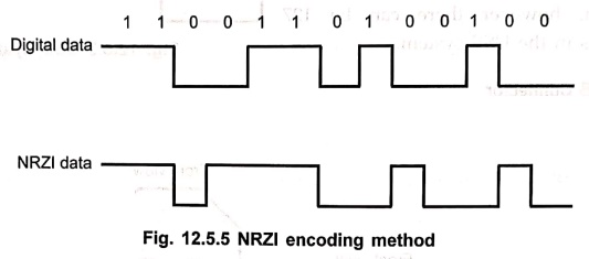
The USB uses NRZI (non–return–to zero, inverted) data encoding method for
transmitting data packets. In this method, the signal level does not change for
the transmission of logic 1. However, it is inverted for each change to a logic
0. This is illustrated in Fig. 12.5.5. In this method data bits are always
transmitted beginning with the least significant bit first, followed by
subsequent bits.
•
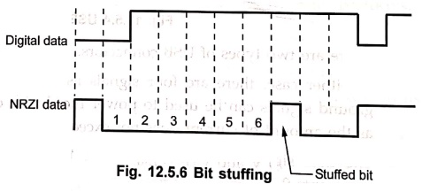
To maintain the signal frequency in the specified range i.e. to achieve
synchronization we have to insert a sync bit in the data stream, if a logic 1
is transmitted for more than six bits in a row. The process of inserting sync
bit is known as bit stuffing.
•
The bit stuffing is illustrated in Fig. 12.5.6. Bit stuffing ensures that the
receiver can maintain synchronization for long strings of logic 1s.
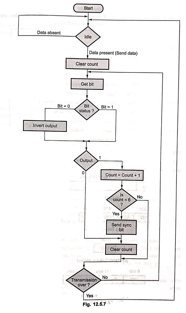
• Fig. 12.5.7 shows the flowchart to generate USB
data from the raw digital serial data.
5. USB Commands
•
USB data is transmitted to particular receptor with the use of USB commands.
•
The communication begins with the transmission of the sync byte (80H).
•
It is followed by the packet identification byte (PID). The PID contains eight
bits, but only the rightmost four bits contain the type of packet. The leftmost
four bits of the PID are the complement form of four rightmost bits.
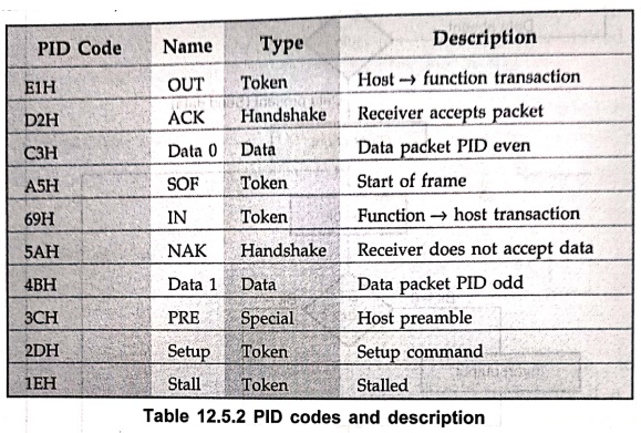
• For example, if a command is 1001, the actual PID byte is 0110 1001. Table 12.5.2 shows the available 4–bit PIDs and their 8–bit codes. The PIDs are also used as token indicators, as data indicators, and for handshaking.
6. USB Packet Format
•
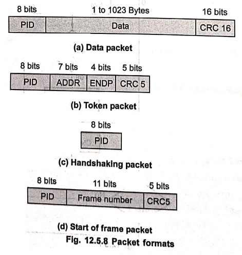
Fig. 12.5.8 shows the formats of data, token, handshaking and start–of frame
packets used on the USB.
•
The data packet begins with PID, then data byte and ends with CRC (cyclic
redundancy check) code.
•
Packets use two types of CRC codes : one is a 5–bit CRC and the other (used for
data packets) is a 16–bit CRC.
•
The 5–bit CRC is generated with the X5 +X2 +1 polynomial.
•
The 16–bit CRC is generated with the X16 +X15 +X2
+1 polynomial.
•
The USB uses the ACK (acknowledge) and NAK (Not acknowledge) tokens to co–ordinate
the transfer of data packets between the host system (host is a PC or other
computer that contain two components : controller and a root hub). (A hub is
device that contains one or more connecters or internal connections to USB devices
along with the hardware to enable communicating with each device and the USB
device.)
•
Once a data packet is transferred from the host to the USB device, the USB
device either transmits and ACK or a NAK token back to the host.
•
If the data and CRC are received without error, the ACK is sent ; otherwise,
the NAK is sent.
•
If the host receives a NAK token, it retransmits the data packet until the
receiver receives it without error.
•
This method of data transfer is known as stop
and wait flow control. In this method, the host has to wait for the client
to send an ACK or NAK before transferring additional data packets.
7. Data Transfer Types
•
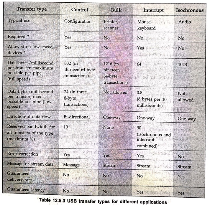
The USB is designed to handle many types of peripherals with varying
requirements for transfer rate, response time, and error correcting. There are
four types of data transfers each handle different needs and a peripheral can
support the transfer types that are best suited for its purpose.
1. Control transfer
•
Control transfers transfers are the only type with functions defined by the USB
specification. These transfers enable the host to read and select
configurations and other settings on the devices being enumerated. Control
transfers may also send custom requests that send and receive blocks of data
for any purpose. All USB devices must support control transfers.
•
This data transfer exchanges configuration, setup, and command information between
the device and host. CRCs check the data and initiate retransmissions when
needed to guarantee the correctness of these packets.
•
Control transfers use message pipes. In a message pipe, each transfer begins
with a Setup transaction containing a request. To complete the transfer, the
host and device may exchange data and status information, or the device may
just send status information. There is always at least one transaction that
sends information in each direction.
•
If the request is one that the device supports, it takes the requested action.
A device may also respond with a code that indicates that it does not support
the ane request.
2. Bulk transfer
•
Bulk transfers are intended for situa tions where the rate of transfer isn't
critical, such as sending a file to a printer or receiving data from a scanner.
In these cases quick transfers are nice, but the data can wait if necessary. If
the bus is very busy with other transfers that have guaranteed transfer rates,
bulk transfers must wait, but if the bus is idle, bulk transfers are very fast.
Only full–speed devices can do bulk transfers. Devices are not required to support
bulk transfers, but a specific device class might require it.
•
This data transfer moves large amounts of data when timely delivery is not
critical. Typical applications include printers and scanners. Bulk transfers
are fillers, claiming unuse USB bandwidth when nothing more important is going
on. CRCs protect these packets.
3. Interrupt transfer
•
Interrupt transfers are for devices that must receive the host's or device's
attention quickly. Other than control transfers, interrupt transfers are the
only way that low speed devices can transfer data. A keyboard or mouse can use
interrupt transfers to send keypress or mouse movement data. Both full and low
speed devices can do interrupt transfers. Devices aren't required to support
interrupt transfers, but a specific device class might require it.
•
This data transfers, though not interrupt in the CPU diverting sense, poll
devices to see if they need service. Peripherals exchanging small amounts of
data that need immediate attention (such as mice and keyboards) use interrupt
transfers. Error checking validates the data.
4. Isochronous transfer (USB for audio devices)
•
Isochronous transfers are for devices
that must transfer data at a constant rate, such as audio files to be played in
real time, or other data that needs a guaranteed delivery rate or time. This is
the only transfer type that doesn't support automatic hare–transmitting of data
received with errors, so occasional errors must be acceptable. Only full speed
devices can do isochronous transfers. Devices are not required to support
isochronous transfers, but a specific device class might require it.
•
This data transfer handling trimming data like an audio or video device. It is
time sensitive information so within limitation it has guaranteed access to a
USB bus. No error checking occurs so the system must tolerate occasional
scrambled bytes.
•
Above three transfers namely Bulk transfer, Interrupt transfer, and Isochronous
transfer use Stream Pipes.
•
In a stream pipe, the data has no format defined by the USB specification. The
receiving device just accepts whatever arrives. The device firmware or host
software can then process the data in whatever way is appropriate for the
application. Of course, even with stream data, the sending and receiving
devices will need to agree on some type of format.
Review Questions
1. Write short note on
advantages of USB over older I/O bus architectures.
2. Write notes on :
USB.
3. Explain the
protocols of USB.
4. Discuss the salient
features of the USB operation.
5. What are the
advantages of USB interface?
3. SATA
•
A serial advanced technology attachment (serial ATA, SATA or S–ATA) is a
computer bus interface that connects host bus adapters with mass storage
devices like optical drives and hard drives.
•
As its name implies, SATA is based on serial signaling technology, where data
is transferred as a sequence of individual bits
•
This interface is commonly used to connect hard disk drives to a host system
such as a computer motherboard.
•
The first version of SATA communicated at 150 megabytes per second (MBps). The
standard was soon upgraded to 300 MBps in 2004 and 600 MBps in 2009–estimated
to be sufficient to accommodate 10 years of advances in device throughput.
Features
• Low Voltage Requirement
: SATA
operates on 500 mV (0.5 V) peak–to–peak signaling. This help in promoting a
much low interference and crosstalk between conductors.
• Hot Plugging :
This feature helps users to change or remove storage devices even when the
computer is running.
• Staggered Spin–Up :
Allows sequential hard disk drive startup, which helps even out power load
distribution during system booting.
• Native Command
Queuing (NCQ) : Usually, the commands reach a disk for
reading or writing from different locations on the disk. When the commands are
carried out based on the order in which they appear, a substantial amount of
mechanical overhead is generated because of the constant repositioning of the
read/write head. SATA II drives use an algorithm to identify the most effective
order to carry out commands. This helps to reduce mechanical overhead and
improve performance.
• Port Multipliers :
Allows the connection of up to 15 drives to a SATA controller. This facilitates
the building of disk enclosures.
• Port Selectors : Facilitates
redundancy for two hosts connected to a single drive, allowing the second host
to take over in the event of a primary host failure.
Simplified construction
:
PATA cables had 40–pin/80–wire ribbon cable. This was complex in structure. In
comparison, SATA had a single 7 pin data cable and a 15 pin power cable. This
cable resulted in a higher signaling rate, which translates to faster
throughput of data.
• Differential
Signaling : SATA uses differential signaling.
Differential signaling is a technology which uses two adjacent wires to
simultaneously the in–phase and out–of–phase signals. Thus, it is possible to
transfer high–speed data with low operating voltage and low power consumption
by detecting the phase difference between the two signals at the receiver's
end.
•
High data transfer rate : SATA has a
high data transfer rate of 150 / 300 / 600 MBs/second. This capability of SATA
allows for faster program loading, better picture loading and fast document
loading.
• Large Cable Length :
SATA cable can be of length up to 1 meter, whereas PATA cable can only have a
length of maximum 18 inches.
Operating
Modes
•
SATA operates on two modes :
■ IDE mode :
IDE stands for Integrated Drive Electronics. This mode is used to provide
backward compatibility with older hardware, which runs on PATA, at low
performance.
■ AHCI mode :
AHCI is an abbreviation for Advanced Host Controller Interface. AHCI is a high–performance
mode that also provides support for hot–swapping.
•
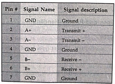
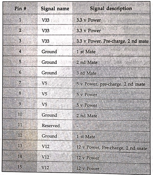
The Serial ATA [SATA] bus is defined over two separate connectors, one
connector for the data lines and one for the power lines.
SATA Data
pinout
SATA
Power pinout
Review Questions
1. Write a short note
on SATA.
2. List the features
of SATA.
Digital Principles and Computer Organization: Chapter 12: IO Systems : Tag: : - I/O Devices and Interface Standards
Digital Principles and Computer Organization: Chapter 12: IO Systems
Under Subject

Digital Principles and Computer Organization
CS25C06 2nd Semester AIDS, CSE, IT, CSE(CY) Dept | 2025 Regulation | 2nd Semester 2025 Regulation
Related Subjects

English Essentials II
EN25C02 2nd Semester | 2025 Regulation | 2nd Semester 2025 Regulation

Tamils and Technology தமிழர்களும் தொழில்நுட்பமும்
UC25H02 2nd Semester | 2025 Regulation | 2nd Semester 2025 Regulation

Linear Algebra
MA25C02 2nd Semester | 2025 Regulation

Applied Physics (CSIE) II
PH25C03 2nd Semester AIDS, CSE, IT, CSE(CY) Dept | 2025 Regulation | 2nd Semester 2025 Regulation
Digital Principles and Computer Organization
CS25C06 2nd Semester AIDS, CSE, IT, CSE(CY) Dept | 2025 Regulation | 2nd Semester 2025 Regulation

Basic Electrical and Electronics Engineering
EE25C01 2nd Semester | 2025 Regulation | 2nd Semester 2025 Regulation

Python for Data Science
AD25201 2nd Semester AIDS Dept | 2025 Regulation | 2nd Semester 2025 Regulation

Re-Engineering for Innovation
ME25C05 2nd Semester | 2025 Regulation | 2nd Semester 2025 Regulation

Python for Data Science - Laboratory
AD25201 2nd Semester AIDS Dept | 2025 Regulation | 2nd Semester 2025 Regulation