Basic Electronics and Electrical Engineering: Chapter 7: Basics of Power Systems
Circuit Breaker
Types, Working Principle, Operation, Advantages
Electrical circuits breaker is a switching device which can be operated manually and automatically for the controlling and protection of electrical power system, respectively.
CIRCUIT
BREAKER
Electrical circuits
breaker is a switching device which can be operated manually and automatically
for the controlling and protection of electrical power system, respectively.
The modern power system deals with a huge power network and huge numbers of
associated electrical equipments. During short circuits fault or any other type
of electrical fault, these equipments, as well as the power network, suffer a
high stress of fault current, which in turn damage the equipment and networks
permanently. For saving these equipment and the power networks, the fault
current should be cleared from the system as quickly as possible. Again after
the cleared, the system must come to its normal working condition as soon is
possible for supplying reliable quality power to the receiving ends. The
circuits breaker is the special device all the required switching operations
during current carrying condition.
A circuits breaker
essentially consists of fixed and moving contacts, called electrodes. Under
normal operating conditions, these contacts remain closed and will not open
automatically until and unless the system becomes faulty. The contacts can be
opened manually or by remote control whenever desired. When a fault occurs in
any part of the system, the trip coils of the breaker get energized and the
moving contacts are pulled apart by some mechanism, thus opening the circuits.
The main types of
circuits breakers are
(i) Miniature circuits
breakers (MCB)
(ii) Earth leakage
circuits breakers (ELCB) or Residual Current Breaker (RCCB)
(iii) Air blast
Circuits Breaker (ACB)
(iv) Molded Case
Circuits Breakers (MCCB)
(v) Vacuum Circuits
Breaker (VCB)
(vi) SF6
Circuits Breaker
1. Miniature Circuit Breaker (MCB)
Minimum circuits
breakers are electromechanical devices which protect an electrical circuits
from over currents. Over currents in an electrical circuits may results from
short circuits overload, or faulty design. An MCB is better alternative than
fuse, since it does not require replacement once an overload is detected. An
MCB functions by interrupting the continuity of electrical flow through the
circuits once a fault is detected. In simple terms, MCB is a switch which
automatically turns off when the current flowing through it passes the maximum
allowable limit. Generally MCB is designed to protect against over current and
over temperature faults (over heating).
Working Principle
There are two contact ‒
one is fixed and the other is moveable. When the current exceeds the predefined
limit, a solenoid forces the moveable contact to open (ie., disconnect from the
fixed contact) and the MCB turns off, thereby stopping the current from flowing
in the circuits.
Operation
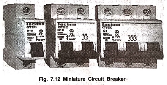
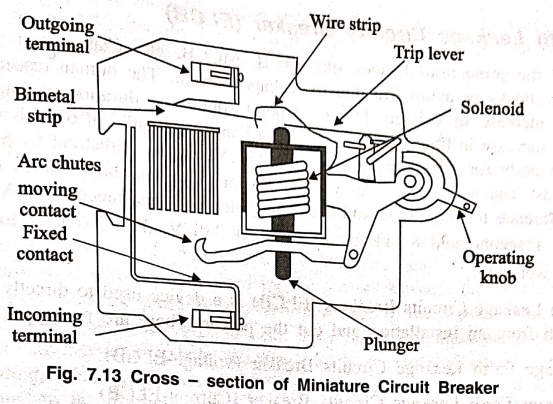
An image of MCB is
shown in figure (7.12) and internal parts of an MCB are shown in figure (7.13).
It mainly consists of one bi‒ metallic strip, one trip coil and one hand
operated on‒off lever. Electric current carrying path of a MCB is as follows‒
as follows - first left hand side power terminal‒then bimetallic strip ‒ then
current coil - then moving contact - then fixed contact and - lastly right hand
side power terminal, and all are arranged in series.
If circuits is overload
for a long time, the bi‒metallic strip becomes over heated and deformed. This
deformation of bi‒metallic strip causes displacement of latch point. The moving
contact of the MCB is so arranged by means of spring, with this latch point,
that a little displacement of latch causes releases of spring and makes the
moving contact to move for opening the MCB. The current coil or trip coil
placed in such a manner that during SC faults, the MMF of that coil causes its
plunger to hit the the same latch point and force the latch to be displaced.
Hence, the MCB will
open in the same manner. Again when operating lever of the MCB is operated by
hand, that means when we make the MCB at off position manually, the same latch
point is displaced as a result moving contact separated from fixed contact in
same manner. So, whatever may be the operating mechanism, i.e., may be due to
deformation of bi‒metallic strip or may be due to increased MMF of trip coil or
may be due to manual operation actually the same latch point is displaced and
the deformed spring is released, which is ultimately responsible for movement
of the moving contact. When the moving contacts is separated from fixed
contact, there may be a high chance of arc.
This are then goes up
thorough the arc runner and enters into arc splitters and is finally quenched.
When we switch on the MCB, we actually reset the displaced operating latch to
its previous on position and make the MCB ready for another switch off or trip
operation.
These are available in
single pole, double pole, triple pole, and four pole versions with neutral
poles, if required. The normal current ratings are available from 0.5‒63 A with
a symmetrical short circuits rupturing capacity of 3‒10 kA, at a voltage level
of 230/440 v. MCBs are generally designed to trip within 2.5 millisecond when
an over current fault arises. In case of temperature rise or over heating it
may take 2 seconds to 2 min. For the MCB to trip.
Advantages
(i) MCBs are replacing
the re‒wireable switch i.e., fuse units for low power domestic and industrial
applications.
(ii) The disadvantages
of fuses, like low SC interrupting capacity (say 3 kA). Arc overcome with high
SC breaking capacity of 10 KA.
(iii) MCB is
combination of all three functions in a wiring system like switching, overload
and short circuits protection. Overload protection can be obtained by using bi‒metallic
strips where as shorts circuits protection can be obtained by using solenoid.
2. Earth Leakage Circuits Breaker (ELCB)
None of the protection
devices like MCB, MCCB, etc. Can protect the human life against electric shocks
or avoid fire due to leakage current. The human resistance noticeably drops with
an increase in voltage. It also depends upon the duration of impressed voltage
and drops with increase in time. As per IS code, a contact potential of 65 V is
within tolerable limit of human body for 10 seconds, where as 250 V can be
withstood by human body for 100 milliseconds. The actual effect of current
thorough human body varies from person to person with reference to magnitude
and duration. The body resistance at 10 V is assessed to be 19 kΩ for 1 second
and 8 kΩ for 15 min. At 240 V, 3 to 3.6 kΩ for dry skin and 1‒1.2 kΩ for wet
skin.
An Earth Leakage
Circuits Breakers (ELCB) is a device used to directly detect currents leaking
to earth from an installation and cut the power. There are two types of ELCBS:
(i) Voltage Earth
Leakage Circuits Breaker (voltage‒ELCB)
(ii) Current Earth
Leakage Circuits Breaker (Current‒ELCB)
(i) Voltage Earth Leakage Circuits Breaker (voltage ‒ELCB)
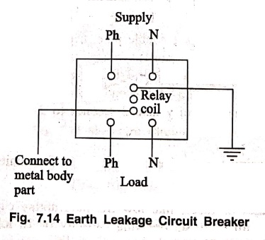
Voltage ‒ELCB is a
voltage operated circuits breakers. The device will function when the current
passes thorough the ELCB. Voltage‒ELCB contains relay coil and one end of the
coil is connected to metallic load body and the other end is connected to
ground wire as shown in figure (7.14). If the voltage of the equipment body
rises (by touching phase to metal part or insulation failure of equipment),
which could cause the difference between earth and load body voltage and the
danger of electric shock will occur. This voltage difference will produce an
electric current from the load metallic body and phase through the loop to the Earth.
When voltage on the
equipment metallic body rises to danger level i.e., which exceed to 50 V, the
flowing current through relay loop could move the relay contact by
disconnecting the supply current avoid from any danger electric shock. The ELCB
detects fault currents from line to the earth (ground) wire within the
installation it protects. If sufficient voltage appears across the ELCB's
sensing coil, it will switch off the power, and remain off until manually
reset. A voltage
- sensing ELCB does not
sense fault current from line to any other earthed body.
(ii) Current Earth Leakage Circuits Breaker (Current‒ELCB)
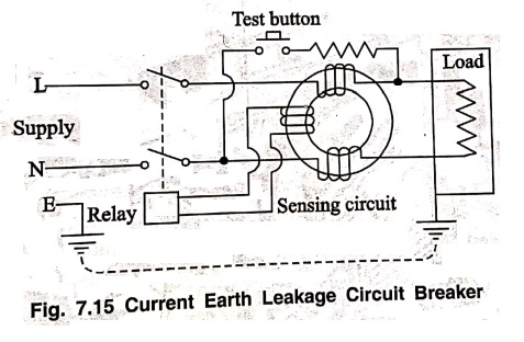
Current ‒ELCB is a
current operated circuits breaker which is a commonly used ELCB. Current‒ELCB
consists of a 3‒winding transformer, which has two primary windings and one
secondary winding as shown in figure (7.15). Neutral and line wires act as the
two primary windings. A wire wound coil is the secondary winding. The current
thorough the secondary winding is zero at the balanced condition. In the
balanced condition, the flux due to current through the phase wire will be
neutralized by the current through the neutral wire, since the current which
flows from the phase will be returned back to the neutral. When a fault occurs,
a small current will flow to the ground also. This makes an unbalanced between
line and neutral currents and creates an unbalanced magnetic filed. This
induces a current through the secondary winding, which is connected to the
sensing circuits. This will sense the leakage and send a signal to the tripping
system and trips the contact.
3. Molded Case Circuits Breaker (MCCB)
Molded case circuits
breakers are electromechanical devices which protect a circuits from over
current and short circuits. They provide over current and short circuits
protection for circuits ranging from 63A up to 3000 A. Their primary function
are to provide a means manually open a circuits and automatically open a
circuits under overload or short circuits conditions respectively. The over
current, in an electrical circuits, may result from short circuits, overload of
faulty design.
MCCB is an alternative
to a fuse, since it does not require replacement once an overload is detected.
Unlike a fuse, an MCCB can be easily reset after a fault and offer improved
operational safety and convenience without incurring operating cost.
Molded case circuits
breakers generally have a
(i) Thermal element for
over current and
(ii) Magnetic element
for short circuits release which has to operate faster.
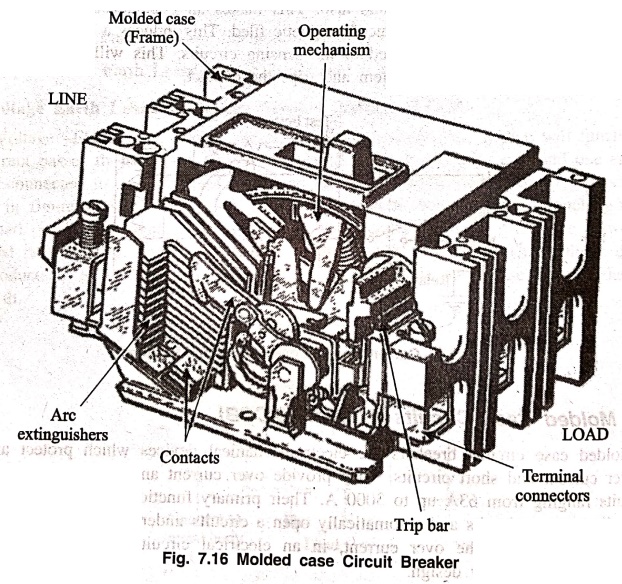
The MCCBS are comprised
of five major components such as molded case or frame operating mechanism, arc
extinguishers, contacts and trip components as shown in figure (7.16) MCCB are
manufactured such that the end user will not have access to internal workings
of the over-current protection device. Generally constructed of two pieces of
heavy‒duty electrically insulated plastic, these halves are riveted together to
form the whole. Inside the plastic shell is series of thermal elements and a
spring‒loaded trigger. When the thermal element gets too warm, from an over
current situation, the spring trips, which in turn will shut off the electrical
circuits.
Operating mechanism
At its core, the
protection mechanism employed by MCCBS is based on the same physical principles
used by all type of thermal - magnetic circuits breakers.
Overload protection is
accomplished by means of a thermal mechanism. MCCBs have a bimetallic contact
that expands and contacts in response to changes on temperature. Under normal
operating conditions, the contact allows electric current through the MCCB.
However as soon as the current exceeds the adjusted trip value, the contact
will start to heat and expend until the circuits the circuit is interrupted.
The thermal protection against overload is designed with a time delay to allow
short duration over current, which is a normal part of operation for many
devices. However, any over current conditions that last more than what is
normally expected represent an overload, and the MCCB is tripped to protect the
equipment and personnel.
On the other hand,
fault protection is accomplished with electromagnetic induction, and the
response is instant. Fault currents should be interrupted immediately, no
matter if their duration is short or long.
Whenever a fault
occurs, the extremely high current induces a magnetic field in a solenoid coil
located inside the breaker ‒ this magnetic induction trips a contact and
current it interrupted. As a complement to the magnetic protection mechanism,
MCCBs have internal arc dissipation measure to facilitate interruption.
As with all types of
circuits breakers, the MCCB includes a disconnection switch which is used to
trip the breaker manually. It is used whenever the electric supply must be
disconnected to carry out field work such as maintenance or equipment upgrades.
Applications
Molded case circuits
circuits breakers can have very high current ratings, which allows them to be
used in heavy duty applications such as main electric feeder protection,
capacitor bank protection, generator protection, welding applications, low
current application that require adjustable trip setting and motor protection.
Basic Electronics and Electrical Engineering: Chapter 7: Basics of Power Systems : Tag: Basic Engineering : Types, Working Principle, Operation, Advantages - Circuit Breaker
Basic Electronics and Electrical Engineering: Chapter 7: Basics of Power Systems
Under Subject

Basic Electronics and Electrical Engineering
EE25C04 1st Semester ECE Dept | 2025 Regulation | 2nd Semester 2025 Regulation
Related Subjects

English Essentials I
EN25C01 1st Semester | 2025 Regulation | 1st Semester 2025 Regulation

தமிழர் மரபு - Heritage of Tamils
UC25H01 1st Semester | 2025 Regulation | 1st Semester 2025 Regulation

Applied Calculus
MA25C01 Maths 1 M1 - 1st Semester | 2025 Regulation | 1st Semester 2025 Regulation

Applied Physics I
PH25C01 1st Semester | 2025 Regulation | 1st Semester 2025 Regulation

Applied Chemistry I
CY25C01 1st Semester | 2025 Regulation | 1st Semester 2025 Regulation

Makerspace
ME25C04 1st Semester | 2025 Regulation | 1st Semester 2025 Regulation

Computer Programming C
CS25C01 1st Semester | 2025 Regulation | 1st Semester 2025 Regulation

Computer Programming Python
CS25C02 1st Semester | 2025 Regulation | 1st Semester 2025 Regulation

Fundamentals of Electrical and Electronics Engineering
EE25C03 1st Semester | 2025 Regulation | 1st Semester 2025 Regulation

Introduction to Mechanical Engineering
ME25C03 1st Semester | 2025 Regulation | 1st Semester 2025 Regulation

Introduction to Civil Engineering
CE25C01 1st Semester Civil Department | 2025 Regulation | 1st Semester 2025 Regulation

Essentials of Computing
CS25C03 1st Semester - AID CSE IT Department | 2025 Regulation | 1st Semester 2025 Regulation

Applied Physics I Laboratory
PH25C01 1st Semester practical Laboratory Manual | 2025 Regulation | 1st Semester Laboratory 2025 Regulation

Applied Chemistry I Laboratory
CY25C01 1st Semester practical Laboratory Manual | 2025 Regulation | 1st Semester Laboratory 2025 Regulation

Computer Programming C Laboratory
CS25C01 1st Semester practical Laboratory Manual | 2025 Regulation | 1st Semester Laboratory 2025 Regulation

Computer Programming Python Laboratory
CS25C02 1st Semester practical Laboratory Manual | 2025 Regulation | 1st Semester Laboratory 2025 Regulation

Engineering Drawing
ME25C01 EEE Mech Dept | 2025 Regulation | 2nd Semester 2025 Regulation
Basic Electronics and Electrical Engineering
EE25C04 1st Semester ECE Dept | 2025 Regulation | 2nd Semester 2025 Regulation