Basic Electronics and Electrical Engineering: Chapter 7: Basics of Power Systems
Protection of Power System
Protection of Power System: 1. Switch gear 2. Circuit breaker 3. Relay
PROTECTION
OF POWER SYSTEM
A great demand for
electrical energy is a notable feature of modern civilization. In general the
electric energy is needed for lighting, heating, domestic appliances,
industrial electrical machinery and electric traction. It is desirable to protect
the power system from harm during fault conditions and to ensure maximum
continuity of supply. For this purpose, all electrical equipments and system
under both normal and abnormal conditions must be provided to switch on or off.
This is achieved by an apparatus called switch gear. A switch gear essentially
consists of switching and protecting devices such as fuses, switches, circuit
breaker, relays, lighting arresters etc.
1. Switch gear
The apparatus used for
switching, controlling and protecting the electrical apparatus and equipment is
known as switch gear. During normal conditions, switch gear permits to switch
on or off generators, transmission lines, distributors and other electrical
equipment. When short circuit or fault occurs on any part of power system, a
heavy 'current flows through the equipment, threatening damage to the equipment
and interruption of service to the consumers. However, the switch gear detects
the fault and disconnects the unhealthy section from the system.
The switch gear consists
of switches, fuses, circuit breakers, relays and other equipments. The switches
may be classified into air switches and oil switches. The contacts of the
former are opened in air and that of the latter are opened in oil.
A fuse is a short piece
of wire or thin strip which melts when excessive current flows through it for sufficient
time. It is inserted in series with the circuit to be protected. Under normal
operating conditions, the fuse element is at a temperature below its melting
point. Therefore, it carries the normal load current without overheating. When
a over load or fault occurs, the current through the fuse element increases
beyond its rated capacity. This raises the temperature and the fuse element
melts, disconnecting the circuits protected by it.
2. Circuit breaker
A circuit breaker is an
equipment which can open or close a circuit under normal and abnormal
conditions. Under normal conditions, it can be operated manually. Under normal
conditions, it can be operated automatically.

Fig 7.4 shows the
circuit breaker with relay connection. The relay coil is connected to the
secondary of a current transformer. The primary carries the line current of the
phase that has to be protected. If the line current exceeds a preset limit, the
secondary current will cause the relay contacts C1 C2 to close.
When C1 C2 contacts get closed, the tripping coil is
energised by an auxiliary d.c source. This causes the main contacts to open,
thus interrupting its circuit.
3. Relay
A relay is a device
which detects the fault and supplies information to the breaker for circuit
interruption. Fig. 7.5 shows the typical relay circuit. The relay circuit
consists three major parts.
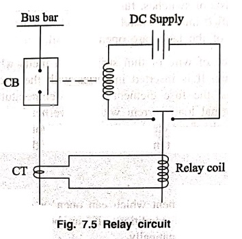
In an current
transformer, the primary winding is connected in series with the circuit to be
protected. The secondary winding of current transformer is connected to the
relay operating coil. The tripping coil circuit consists of a source of supply,
trip coil of circuit breaker and relay contacts.
Under normal
conditions, the emf induced in the secondary winding of CT is small and the
current flowing in the relay operating coil is insufficient to close the relay
contacts. The contacts of the circuit breaker remain closed and it carries
normal load current. When a fault occurs, a large current flows through the
primary of CT. This increases the secondary emf and hence the current through
the relay operating coil. The relay contacts are closed and trip the coil of
the circuit breaker is energised to open the contacts of the circuit breaker.
Basic Electronics and Electrical Engineering: Chapter 7: Basics of Power Systems : Tag: Basic Engineering : - Protection of Power System
Basic Electronics and Electrical Engineering: Chapter 7: Basics of Power Systems
Under Subject

Basic Electronics and Electrical Engineering
EE25C04 1st Semester ECE Dept | 2025 Regulation | 2nd Semester 2025 Regulation
Related Subjects

English Essentials I
EN25C01 1st Semester | 2025 Regulation | 1st Semester 2025 Regulation

தமிழர் மரபு - Heritage of Tamils
UC25H01 1st Semester | 2025 Regulation | 1st Semester 2025 Regulation

Applied Calculus
MA25C01 Maths 1 M1 - 1st Semester | 2025 Regulation | 1st Semester 2025 Regulation

Applied Physics I
PH25C01 1st Semester | 2025 Regulation | 1st Semester 2025 Regulation

Applied Chemistry I
CY25C01 1st Semester | 2025 Regulation | 1st Semester 2025 Regulation

Makerspace
ME25C04 1st Semester | 2025 Regulation | 1st Semester 2025 Regulation

Computer Programming C
CS25C01 1st Semester | 2025 Regulation | 1st Semester 2025 Regulation

Computer Programming Python
CS25C02 1st Semester | 2025 Regulation | 1st Semester 2025 Regulation

Fundamentals of Electrical and Electronics Engineering
EE25C03 1st Semester | 2025 Regulation | 1st Semester 2025 Regulation

Introduction to Mechanical Engineering
ME25C03 1st Semester | 2025 Regulation | 1st Semester 2025 Regulation

Introduction to Civil Engineering
CE25C01 1st Semester Civil Department | 2025 Regulation | 1st Semester 2025 Regulation

Essentials of Computing
CS25C03 1st Semester - AID CSE IT Department | 2025 Regulation | 1st Semester 2025 Regulation

Applied Physics I Laboratory
PH25C01 1st Semester practical Laboratory Manual | 2025 Regulation | 1st Semester Laboratory 2025 Regulation

Applied Chemistry I Laboratory
CY25C01 1st Semester practical Laboratory Manual | 2025 Regulation | 1st Semester Laboratory 2025 Regulation

Computer Programming C Laboratory
CS25C01 1st Semester practical Laboratory Manual | 2025 Regulation | 1st Semester Laboratory 2025 Regulation

Computer Programming Python Laboratory
CS25C02 1st Semester practical Laboratory Manual | 2025 Regulation | 1st Semester Laboratory 2025 Regulation

Engineering Drawing
ME25C01 EEE Mech Dept | 2025 Regulation | 2nd Semester 2025 Regulation
Basic Electronics and Electrical Engineering
EE25C04 1st Semester ECE Dept | 2025 Regulation | 2nd Semester 2025 Regulation