Digital Principles and Computer Organization: Chapter 4: Combinational Circuits
Floating Point Operations
1. Addition and Subtraction: Overflows and Underflows in Mantissa and Exponent, Flowchart for Floating Point Addition and Subtraction, Hardware Implementation of Floating Point Addition/ Subtraction 2. Multiplication and Division. Questions: 1. State and explain the rules in arithmetic operations on floating point numbers. 2. Explain the working of floating point adder/subtractor. 3. Explain the floating point Add/Subtract rules. With a detailed flowchart explain how floating point addition/subtraction is performed. 4. Derive and explain an algorithm for adding and subtracting two floating point binary numbers. 5. Draw the hardware implementation of floating point operations. 6. Explain the rules for basic arithmetic operations of floating point numbers. 7. Explain how floating point addition is carried out in a computer system. Give an example for a binary floating point addition. 8. Explain briefly about floating point addition and subtraction alogorithms. 9. Design an arithmatic element to perform the basic floating point operations. 10. Explain floating point addition algorithm with a neat block diagram. 11. How do you perform the floating point multiplication and division ? 12. Rules of multiplication. 13. Rules of division.
Floating Point
Operations
In
this section we are going to see general procedures for addition, subtraction, multiplication
and division of floating point numbers.
1. Addition and Subtraction
Consider
two floating point numbers :
A
= m1. re1 and
B
= m2.re2 Assume : e1 ≥ e2
Let
us see the rules for addition and subtraction.
Step 1:
Select the number with a smaller exponent and shift its mantissa right, a
number of steps equal to the difference in exponents | e2 – e1|
. For examples, if the numbers are 1.75 ×10² and 6.8 ×10⁴,
then the number 1.75 ×10² is selected and converted to 0.0175 x10⁴.
Step 2 :
Set the exponent of the result equal to the larger exponent.
Step 3 :
Perform addition/subtraction on the mantissas and determine the sign of the result.
Step 4 :
Normalize the result, if necessary.
Example: 1
Perform addition and
subtraction of single precision floating point numbers A and B, where A =
44900000H and B = 42A00000H
Solution :
Step 1:
Represent numbers in single precision format
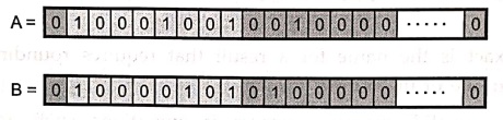
Exponent
for A = 1 0 0 0 1 0 0 1 = 137
Actual
exponent = 137 – 127 (Bias) = 10
Exponent
for B = 1 0 0 0 0 1 0 1 = 133
Actual
exponent = 133 – 127 (Bias) = 6
Number
B has smaller exponent with difference 4. Hence its mantissa is shifted right
by 4–bits as shown below.
Step 2 :
Shift mantissa : Shifted mantissa of
B = 0 0 0 0 0 1 0 0 ... 0
Step 3 :
Add mantissas :
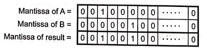
As
both numbers are positive, sign of the result is positive.

•
In subtraction, two mantissas are subtracted instead of addition and the sign
of greater mantissa is assigned to the result.
Step 4 :
Subtract mantissa

Mantissa
for A is greater than mantissa for B therefore sign of result is sign of A.

Example: 2
Add the numbers (0.5)10
and (0.4375)10 using the floating point addition.
Solution :
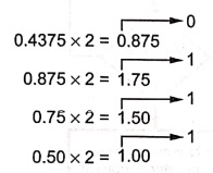
(0.5)10 = (0.1)2 = 1.0×2–1
(0.4375)10 = (0.0111)2 =
(1.110)2×2–2
Step 1 :
Shift right the number with lesser exponent until its exponent matches the
larger number (1.110)2×2–2 = 0.111×2–1
Step 2 :
Add
1.0
× 2–1 = 0.111×2–1 = 1.111×2–1
1. Overflows and Underflows in Mantissa and Exponent
Mantissa overflow :
The addition of two mantissas of the same sign may result in a carryout of the
most significant bit. If so, the mantissa is shifted right and the exponent is
incremented.
Mantissa underflow :
In the process of aligning mantissas, digits may flow off the right end of the
mantissa. In such case truncation methods such as chopping, rounding are used.
Exponent overflow :
Exponent overflow occurs when a positive exponent exceeds the maximum possible
exponent value. In some systems this may be designated as + ∞ or – ∞
Exponent underflow :
Exponent underflow occurs when a negative exponent exceeds the maximum possible
exponent value. In such cases, the number is designated as zero.
2. Flowchart for Floating Point Addition and Subtraction
Fig.
4.15.1 (a) and (b) shows the flowcharts for floating point addition and
subtraction.
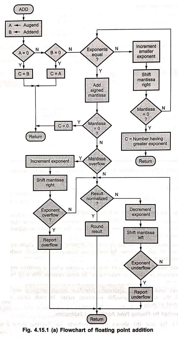
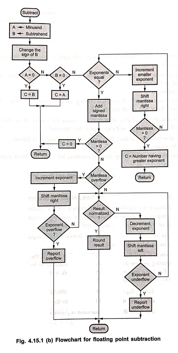
Phase 1 : Changing sign
of B for subtraction and zero check.
•
Addition and subtraction are identical except for a sign change in case of
subtraction.
•
If either operand is zero, the other is reported as the result.
Phase 2 : Align
mantissa
•
The mantissa of the smaller exponent is shift right a number of times equal to
the difference in exponents.
•
In this process, if mantissa is 0 then the number having higher exponent is
reported as the result.
Phase 3 : Addition
•
Two mantissas are added together, taking into account their sign. Because the
signs may differ and result may be 0.
•
There is also the possibility of mantissa overflow by 1 digit. If so, the
mantissa of the result is shifted right and exponent is incremented by 1.
•
In case of exponent overflow, it is reported and operation is halted.
Phase 4 : Normalization
•
Normalization is achieved by shifting mantissa left until the most significant
digit is non zero.
•
Each shift causes a decrement of the exponent and thus could cause an exponent
underflow.
3. Hardware Implementation of Floating Point Addition/ Subtraction
•
Fig. 4.15.2 shows the hardware implementation for the addition and subtraction
of 32–bit floating point operands that have the single precision format, i.e. 1–bit
for sign, 8–bits or signed exponent and 23–bits for mantissa.
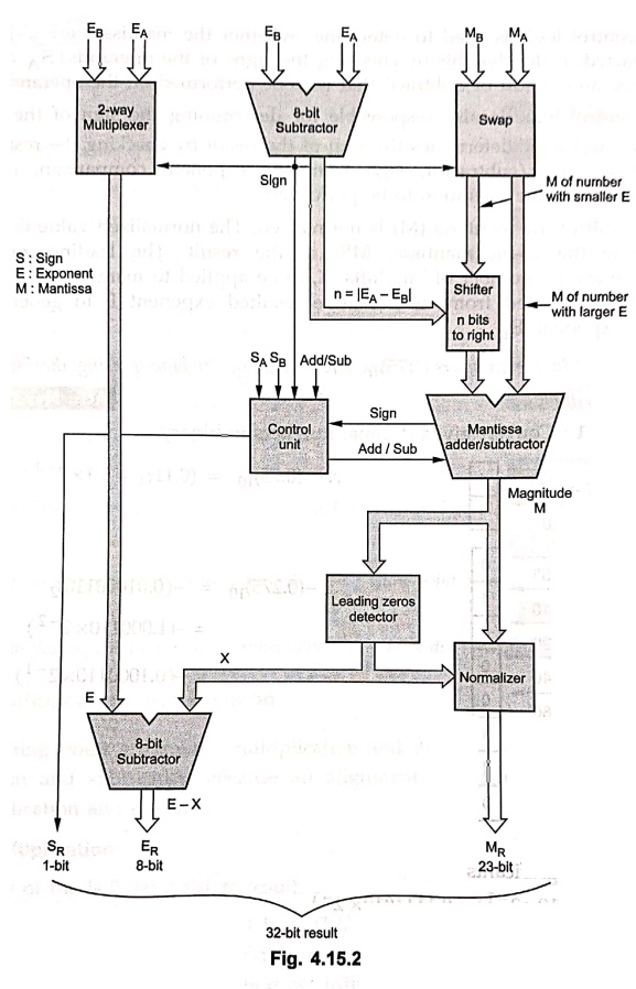
•
To find the difference (shift count n) between two exponents, exponents are
subtracted using 8–bit subtractor.
•
This difference, is sent to the SHIFTER unit. The sign of the difference that
results from comparing exponents determines which mantissa is to be shifted. If
the sign is 0, then EA ≥ EB
and input to SWAP network is 0. This disables swapping and mantissa M B
is sent to the SHIFTER.
•
If the sign is 1, the EA– EB and input to SWAP network is
1. In this case swapping is enabled and mantissa MA is sent to the
SHIFTER.
• The SHIFTER unit shifts the given mantissa n positions to the right.
•
The two way multiplexer is used to set the exponent of the result (E) equal to
the larger exponent, based on the sign
of the difference. The output of multiplexer is
E
= EA if EA ≥ EB
or
E
= EB EA
< EB
•
The control logic is used to determine whether the mantissas are to be added or
subtracted. It decides this by checking the signs of the operands (SA
and SB) and the operation (Add or Subtract) that is to be performed
on the operands.
•
The control logic is also responsible for determining the sign of the result (SR).
The control logic determines the sign of the result by checking the resulted
sign of mantissa adder/subtractor, sign from the exponent comparison, signs of
the operands and the operation to be performed.
•
The result of the mantissa (M) is normalized. The normalized value is truncated
to generate the 23–bit mantissa, MR, of the result. The leading zeros detector
determines the number of bit shifts, X, to be applied to mantissa (M). The
value X is then subtracted from the tentative resulted exponent E to generate
the true result exponent, ER .
Example: 3
Add the numbers (0.75)10
and (–0.275)10 in binary using the Floating point addition
algorithm.
Solution :
Step 1 : Convert
given decimal numbers in binary.
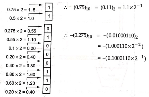
Step 2 :
Add the significants
1.1×2–1
+ (–0.1000110 × 2–1) = 0.1111010
× 2–1
Step 3:
Normalize the sum
0.1111010×2–1
= 1.111010×2–2
Since
127 ≥ – 2 ≥ – 126, there is no overflow or underflow. The bias exponent would
be – 2 + 127 = 125, which is between 1 and 254, the smallest and largest
unreserved biased exponents.)
Step 4 :
Round the sum.
Assuming
8–bit precision the sum is already rounded.
Review Questions
1. State and explain
the rules in arithmetic operations on floating point numbers.
2. Explain the working
of floating point adder/subtractor.
3. Explain the
floating point Add/Subtract rules. With a detailed flowchart explain how
floating point addition/subtraction is performed.
4. Derive and explain
an algorithm for adding and subtracting two floating point binary numbers.
5. Draw the hardware
implementation of floating point operations.
6. Explain the rules
for basic arithmetic operations of floating point numbers.
7. Explain how
floating point addition is carried out in a computer system. Give an example
for a binary floating point addition.
8. Explain briefly
about floating point addition and subtraction alogorithms.
9. Design an
arithmatic element to perform the basic floating point operations.
10. Explain floating
point addition algorithm with a neat block diagram.
2. Multiplication and Division
•
In floating point arithmetic, multiplication and division are somewhat easier
than addition and subtraction because an alignment of mantissas is not required
in multiplication and division.
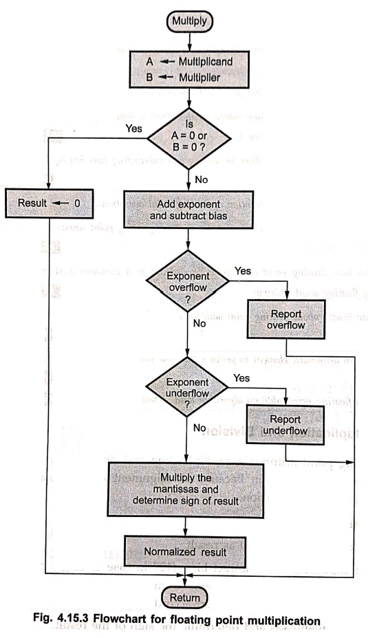
Rules of multiplication
1.
If either of the is 0, report 0 as result.
2.
Add the exponents and subtract bias. (127 in case of single precision numbers
and 1023 in case of double precision numbers). The result may cause exponent
overflow or underflow. If so report accordingly.
3.
Multiply the mantissas and determine the sign of the result.
4.
Normalize the result.
Fig.
4.15.3 shows the flowchart for floating point multiplication.
Example: 4
Multiply the numbers
(0.5)10 and (0.4375)10 using the floating point multiplication.
Solution :
(0.5)10
= 1.0×2–1
(0.4375)10 = (1.110)2 ×2
– 2
Step 1:
Add the exponents without bias
−
1 + (− 2) = –3
Step 2 :
Multiply
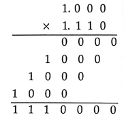
The
product is 1.110000×2 – 3. Since the signs of two operands are same,
is positive.
1.110000×2
– 3 = 0.00111
= 1×2–3 +1 ×2
– 4 +1 ×2 – 5 =
(0.21875)10
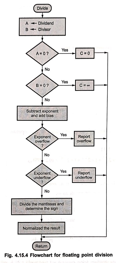
Rules of division
1.
If the dividend is zero, report result as zero.
2.
If the divider is zero, report result as ∞.
3.
Subtract exponents and add bias (127 in case of single precision numbers and
1023 in case of double precision numbers).
4.
Divide the mantissas and determine the sign of the result.
5.
Normalize the result.
Fig.
4.15.4 shows the flowchart for floating point division.
Review Questions
1. How do you perform
the floating point multiplication and division ?
2. Rules of
multiplication.
3. Rules of division.
Digital Principles and Computer Organization: Chapter 4: Combinational Circuits : Tag: : - Floating Point Operations
Digital Principles and Computer Organization: Chapter 4: Combinational Circuits
Under Subject

Digital Principles and Computer Organization
CS25C06 2nd Semester AIDS, CSE, IT, CSE(CY) Dept | 2025 Regulation | 2nd Semester 2025 Regulation
Related Subjects

English Essentials II
EN25C02 2nd Semester | 2025 Regulation | 2nd Semester 2025 Regulation

Tamils and Technology தமிழர்களும் தொழில்நுட்பமும்
UC25H02 2nd Semester | 2025 Regulation | 2nd Semester 2025 Regulation

Linear Algebra
MA25C02 2nd Semester | 2025 Regulation

Applied Physics (CSIE) II
PH25C03 2nd Semester AIDS, CSE, IT, CSE(CY) Dept | 2025 Regulation | 2nd Semester 2025 Regulation
Digital Principles and Computer Organization
CS25C06 2nd Semester AIDS, CSE, IT, CSE(CY) Dept | 2025 Regulation | 2nd Semester 2025 Regulation

Basic Electrical and Electronics Engineering
EE25C01 2nd Semester | 2025 Regulation | 2nd Semester 2025 Regulation

Python for Data Science
AD25201 2nd Semester AIDS Dept | 2025 Regulation | 2nd Semester 2025 Regulation

Re-Engineering for Innovation
ME25C05 2nd Semester | 2025 Regulation | 2nd Semester 2025 Regulation

Python for Data Science - Laboratory
AD25201 2nd Semester AIDS Dept | 2025 Regulation | 2nd Semester 2025 Regulation