Digital Principles and Computer Organization: Chapter 4: Combinational Circuits
Parallel Adder Subtractor
Questions: 1. Design a 4-bit binary adder/subtractor and explain its functions. 2. Indicate how an overflow is detected? 3. Define overflow rule in addition.
Parallel Adder /
Subtractor
•
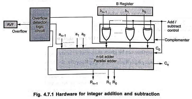
Fig. 4.7.1 shows hardware to implement integer addition and subtraction. It am
consists of n–bit adder, 2's complement circuit, overflow detector logic
circuit and AVF (overflow flag).
•
Number a and number b are the two inputs for n–bit adder. For subtraction, the
subtrahend (number from B register) is converted into its 2's complement form
by making Add/Subtract control signal to the logic one,
•
When Add/Subtract control signal is one, all bits of number b are complemented and
carry zero (C0) is set to one. Therefore n–bit adder gives result as
R = a +  + 1, where + 1 represents 2's complement of number
b.
+ 1, where + 1 represents 2's complement of number
b.
Overflow in integer arithmetic
•
When adding signed numbers, a carry bit beyond the end of the word does not,
serve as the overflow indicator.
•
If we add the numbers + 7 and + 3 in a 4–bit adder, the output is 1010, which
is the code of – 6, a wrong result In this case carry bit from the MSB position
is 0. Similarly, if we add – 5 and 6, we get output = +5, another error. In
this case carry bit from the MSB position is 1.
b.
One thing we can surely say that, the addition of numbers with different signs
cannot cause overflow, because the absolute value of the sum is always smaller
than the absolute value of one of the two operands.
•
From above discussion we can conclude following points :
1.
Overflow can occur only when adding two numbers that have the same sign.
2.
The carry bit from the MSB position is not a sufficient indicator of overflow
when adding signed numbers.
3.
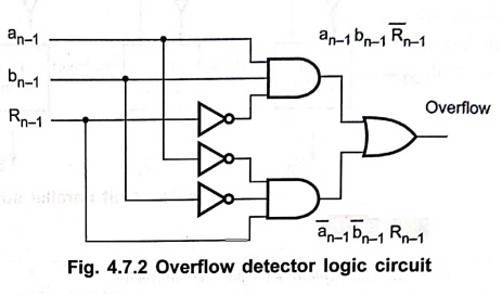
When both operands a and b have the same sign, an overflow occurs when the sign
of result does not agree with the signs of a and b. The logical expression to
detect overflow can be given as

where
an–1
= MSB of number a
bn–1
= MSB of number b
Rn–1
= MSB of the result
Example: 1
Give means to identify
on whether or not an overflow has occurred in 2's complement addition or
subtraction operations. Take one example for each possible situation and
explain. Assume 4–bit registers.
Solution :
Case 1 : Both numbers
positive
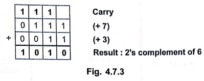
Result
is – 6; it is wrong due to overflow.
Case 2 : Both numbers
negative
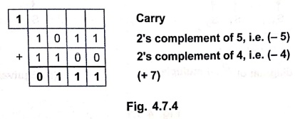
Result
is + 7; it is wrong due to overflow.
Review Questions
1. Design a 4–bit
binary adder/subtractor and explain its functions.
2. Indicate how an
overflow is detected?
3. Define overflow
rule in addition.
Digital Principles and Computer Organization: Chapter 4: Combinational Circuits : Tag: : - Parallel Adder Subtractor
Digital Principles and Computer Organization: Chapter 4: Combinational Circuits
Under Subject

Digital Principles and Computer Organization
CS25C06 2nd Semester AIDS, CSE, IT, CSE(CY) Dept | 2025 Regulation | 2nd Semester 2025 Regulation
Related Subjects

English Essentials II
EN25C02 2nd Semester | 2025 Regulation | 2nd Semester 2025 Regulation

Tamils and Technology தமிழர்களும் தொழில்நுட்பமும்
UC25H02 2nd Semester | 2025 Regulation | 2nd Semester 2025 Regulation

Linear Algebra
MA25C02 2nd Semester | 2025 Regulation

Applied Physics (CSIE) II
PH25C03 2nd Semester AIDS, CSE, IT, CSE(CY) Dept | 2025 Regulation | 2nd Semester 2025 Regulation
Digital Principles and Computer Organization
CS25C06 2nd Semester AIDS, CSE, IT, CSE(CY) Dept | 2025 Regulation | 2nd Semester 2025 Regulation

Basic Electrical and Electronics Engineering
EE25C01 2nd Semester | 2025 Regulation | 2nd Semester 2025 Regulation

Python for Data Science
AD25201 2nd Semester AIDS Dept | 2025 Regulation | 2nd Semester 2025 Regulation

Re-Engineering for Innovation
ME25C05 2nd Semester | 2025 Regulation | 2nd Semester 2025 Regulation

Python for Data Science - Laboratory
AD25201 2nd Semester AIDS Dept | 2025 Regulation | 2nd Semester 2025 Regulation