Computer Organization and Architecture: Chapter 4: Memory and IO
Peripheral Input and Output Devices
Questions: 1. Write a short note on a) Keyboard b) Mouse c) Scanner 2. Write a short note on a) Cathode‒Ray Tubes b) Vector scan display c) Raster scan display d) Beam penetration technique e) Shadow mask technique 3. Explain the working of direct‒view storage tubes. 4. List the advantages and disadvantages of DVST. 5. Write a short note on a) Flat panel display b) Plasma panel display 6. List the important characteristics of video display devices. 7. Write a short note on dot matrix printer. 8. Write a short note on desk jet printer. 9. Write a short note on laser printer. 10. Write short notes on I/O devices.
I/O
Devices
1. Peripheral Input Devices
1. Keyboard
•
The keyboard is a primary input device for any graphics system. It is used for
entering text and numbers, i.e. on graphics data associated with pictures such
as labels x‒y co‒ordinates etc.
•
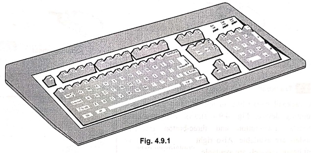
Keyboards are available in various sizes, shapes and styles. Fig. 4.9.1 shows
standard keyboard. It consists of
■
Alphanumeric key
■
Function keys
■
Modifier keys
■
Cursor movement keys
■
Numeric keypad
•
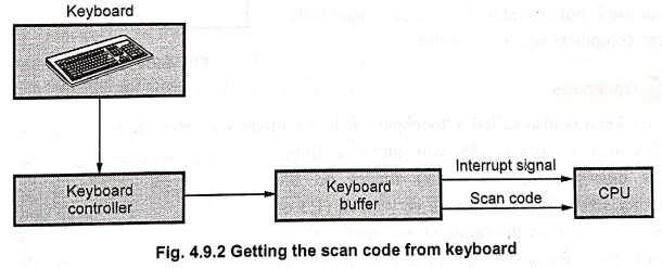
When we press a key on the keyboard, keyboard controller places a code
corresponding to key pressed into a part of its memory, called keyboard buffer. This code is called scan code. The keyboard controller
informs CPU of the computer about the key press with the help of interrupt
signal. The CPU then reads the scan code from the keyboard buffer, as shown in
Fig. 4.9.2.
2. Mouse
•
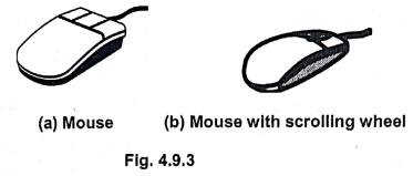
A mouse is a palm‒sized box used to position the screen cursor. It consists of
ball on the bottom connected to wheels or rollers to provide the amount and
direction of movement. One, two or three buttons are usually included on the
top of the mouse for signaling the execution of some operation. Now‒a‒days
mouse consists of one more wheel on the top to scroll the screen pages.
3. Trackball
•
A trackball works like an upside‒down mouse as a pointing device. Fig. 4.9.4
shows some trackball models. Two‒button and three‒button trackball models are
available. Also right handed as well as left handed models are available.
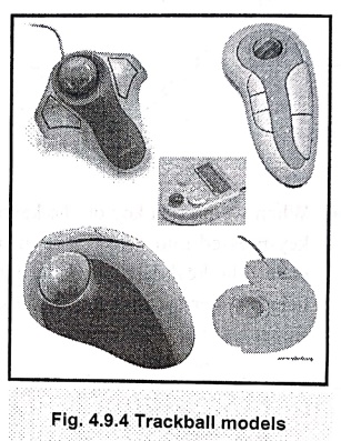
• As shown in Fig. 4.9.4, trackball contains an exposed ball that can be rolled with an index finger or thumb to move the pointer around the screen. A trackball needs less space than a mouse as it is not necessary to move the whole device. The trackballs are mostly used on small work surfaces where sufficient space for mouse is not available. For example, trackballs on laptop computers are very popular.
4. Trackpads
•
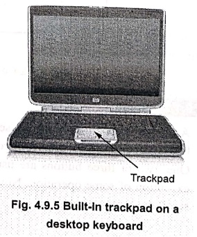
The trackpad is also called a 'touchpad'. It is a stationary pointing device.
It uses a small touch‒sensitive surface. As you move a finger across this
surface, the pointer moves on the computer screen. This surface is very small
(1.5 or 2 inches square), so the required movement of the finger to move the
pointer is very less. So the use of trackpad find less tiring to use as compare
to mouse or trackball. Due to small size, they are useful in notebook
computers. Some notebook computer models use built‒in trackpads. Fig. 4.9.5
shows an example of a built‒in trackpad on a desktop keyboard.
• In some cases, trackpads are separate from the desktop keyboards and are connected to the computer using a cord. There are two types of trackpads.
1. Buttons trackpads :
They include two or three buttons that perform the same functions as mouse
buttons.
2. Strike sensitive
trackpads : They use pads which can be tapped with
fingertip.
5. Touch Screens
•
When you place a fingertip directly on the computer screen, touch‒screen
accepts input. Generally, this method is used to make a choice from a menu. In
most touch‒screen computers the sensors are used on the screen's surface to
detect the touch of a finger. The touch‒screens need dirt‒free environment. The
applications where intuitive interface is an important factor use touch‒screens.
Some of them are listed below.
•
Automated teller machines
•
Public information kiosks
•
Fast‒food restaurants
•
Department stores
•
Drugstores
•
Supermarkets
•
Lottery centers
•
Touch input can be recorded using optical, electrical or acoustical methods.
•
Optical touch screens use a line of infrared light emitting diodes along one
vertical edge and along one horizontal edge of the screen. The opposite
vertical and horizontal edges contain light detectors. These detectors are used
to record which beams are interrupted when the panel is touched. The two
crossing beams that are interrupted indicate the horizontal and vertical co‒ordinates
of the screen position selected.
•
In electrical touch screens, two transparent plates are used. These plates are
separated by a small distance. One plate is coated with conducting material and
other plate is coated with resistive material. When outer plate is touched, it
is forced to contact with the inner plate. This contact creates a voltage drop
across the resistive plate that is used to determine the co‒ordinate values of
the selected screen position.
•
An acoustic touch screens use high frequency sound waves in horizontal and
vertical directions across a glass plate. Touching the screen causes partial
reflection of each wave from finger to the emitter. The screen co‒ordinates of
point of contact are then calculated by measuring time between the transmission
of each wave and its reflection to the emitter.
6. Joystick
•
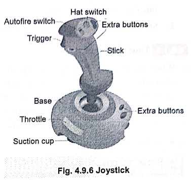
A Joystick is a personal computer input device consisting of a handheld stick
that pivots about one end and transmits its angle in two or three dimensions to
a computer. It has a small, vertical lever called the stick mounted on the base
and used to steer the screen cursor around.
•
Most joysticks are two‒dimensional, having two axes of movement (similar to a
mouse), but three‒dimensional joysticks do exist. A joystick is generally
configured so that moving the stick left or right signals movement along the X
axis, and moving it forward (up) or back (down) signals movement along the Y
axis. In joysticks that are configured for three‒dimensional movement, twisting
the stick left (counter‒ clockwise) or right (clockwise) signals movement along
the Z axis. These three axes XY and Z are, in relation to an aircraft, roll,
pitch and yaw.
•
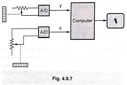
An analog joystick is a joystick which has continuous states, i.e. returns an
angle measure of the movement in any direction in the plane or the space
(usually utilizing potentiometers) and a digital joystick gives only on/off
signals for four different directions and mechanically possible combinations
(such as up‒right, down‒left, and c). Digital joysticks were very common as
game controllers for the video game consoles, arcade machines and home
computers. Additional joysticks often have one or more fire buttons, used to
trigger some kind of action. These are simple on/off switches.
•
Most I/O interface cards for PCs have a joystick (game control) port. Modern
joysticks mostly use a USB interface for connection to the PC.
•
They are mostly popular in racing and flying games. They enable the user to
'drive' or 'fly' through a game. They direct to a character or a vehicle. A
variant of joystick is the racing game controller. It includes an actual
steering wheel and in some cases even foot pedals and gearshifts.
7. Light Pen
•
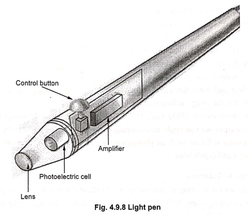
A Light Pen is a pointing device shaped like a pen acts as computer input
device. The tip of the light pen contains a light‒sensitive element which, when
placed against the screen, detects the light from the screen enabling the
computer to identify the location of the pen on the screen.
•
Light pens have the advantage of 'drawing' directly onto the screen. It allows
the user to point to displayed objects or draw on the screen, in a similar way
to a touch screen but with greater positional accuracy. A light pen can work with
any CRT‒based monitor, but not with LCD screens, projectors or other display
devices.
•
The light pen consists of photoelectric cell housed in a pen like case. It
works by sensing the sudden small change in brightness of a point on the screen
when the electron gun refreshes that spot. By noting exactly where the scanning
has reached at that moment, the X,Y position of the pen can be resolved. This
is usually achieved by the light pen causing an interrupt, at which point the
scan position can be read from a special register, or computed from a counter
or timer. The pen position is updated on every refresh of the screen.
•
The response time of the pen is also important. For slow displays transistor
type photo‒ cells such as photo‒diodes are used. These are small, inexpensive
and suitable for hand held operation. The response time is about one
microsecond. For the highspeed displays photo‒ multiplier tube is used. It is
bulky and uses fibre‒optic cable. Now a days improved light pens are available.
These consist of a matrix of fibre optic sensors.
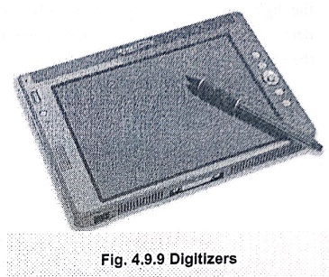
8. Digitizers
•
It is used for applications such as tracing. It consists of flat surface which
can detect the position of a movable stylus.
9. Scanners
•
The scanner is a device, which can be used to store drawing, graphs, photos or
text available in printed form for computer processing. The scanners use the
optical scanning mechanism to scan the information. The scanner records the
gradation of gray scales or colour and stores them in the array. Finally, it
stores the image information in a specific file format such as JPEG, GIF, TIFF,
BMP and so on. Once the image is scanned, it can be processed or we can apply
transformations to rotate, scale or crop the image using image processing
software such as photo‒shop or photo‒paint. Scanners are available in variety
of sizes and capabilities.
Working Principle of Scanners
•
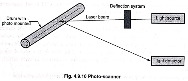
Fig. 4.9.10 shows the working of photo‒scanner. As shown in Fig. 4.9.10, the
photograph is mounted on a rotating drum. A finely collimated light beam is
directed at the photo and the amount of light reflected is measured by a
photocell. As the drum rotates, the light source slowly moves from one end to
the other, thus doing a raster scan of the entire photograph.
•
For coloured photographs, multiple passes are made, using filters in the front
of the photocell to separate out various colours.
•
Other type of scanners are electro‒optical devices that use arrays of light
sensitive Charge Coupled Devices (CCDs) to turn light reflected from, or
transmitted through artwork, photographs, slides etc. into a usable digital
file composed of pixel information.
Resolution and Colour Depth
•
The optical resolution and colour depth are the two important specifications of
the scanner. The photo‒scanners have resolution upto 2000 units per inch.
Resolution of the CCD array is 200 to 1000 units per inch which is less than
the photo‒scanners. The colour depth is expressed in bits. It specifies the
number of colours scanner can capture.
Types of Scanners
•
According to construction the scanners also can be classified as :md
■
Flatbed scanners, also called
desktop scanners, are the most versatile and commonly used scanners. In fact,
this article focuses on the technology as it relates to flatbed scanners.
■
Sheet‒fed scanners are similar to
flatbed scanners except the document is moved and the scan head is immobile. A
sheet‒fed scanner looks a lot like a small portable printer.
■ Handheld scanners
use the same basic technology as a flatbed scanner, but relay on the user to
move them instead of a motorized belt. This type of scanner typically does not
provide good image quality. However, it can be useful for capturing an image
quickly.
■
Drum scanners are used by the
publishing industry to capture incredibly detailed images. They use a
technology called a Photo‒Multiplier
Tube (PMT). In PMT, the document to be scanned is mounted on a glass
cylinder. Located at the center of the cylinder is a sensor that splits light
bounced from the document into three beams. Each beam is sent through a colour
filter into a photo‒multiplier tube where the light is changed into an
electrical signal.
2. Peripheral Output Devices
•
The computer processes input data to produce useful information. This
information can be displayed or viewed on a monitor, printed on a printer or
listened through speakers or a headset, or it can be stored in the secondary
memory device for further processing or future reference. These different ways
of output can be broadly categorized as : Hard
copy output and soft copy output.
1. Soft copy:
The electric version of an output, which usually resides in computer memory
and/or on disk, is known as soft copy.
Soft copy output also includes audio and visual form of output generated using
computer. The soft copy is not a permanent form of output, it can not be
touched.
2. Hard copy:
We obtain hard copy output for our image in several formats using printer or
plotter. Therefore, printers and plotters are also called hard‒copy devices.
The quality of pictures obtained from a hard‒copy device depends on dot size
and the number of dots per inch, or lines per inch, that can be printed, i.e.
it depends on the resolution of printer or plotter. Before going to see working
principle of various plotters and printers we see the important characteristics
of hardcopy devices.
•
The hard copy output is permanent output and relatively stable form of output.
This output is also highly portable.
•
Based on the hard copy and soft copy outputs, the output devices are classified
into : hard copy devices and soft copy output devices. The various
types of output devices are as follows:
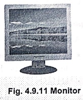
• Monitor:
The computer sends processed data (i.e. output) to the monitor when the user
needs to observe the output.
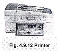
• Printer:
When the user needs hard‒copy (i.e. paper‒copy) of an output, the computer
sends output to the printer.
•
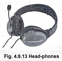
Head‒phones or Speakers : When the
user needs a sound‒ output, the computer sends output to the head‒phones or
speakers.
1. Monitors
•
Monitor is the most commonly used output device in personal computer systems.
The text and graphics can be displayed on the monitor‒screen. The quality of image
displayed on the monitor is determined by two hardware devices, the monitor
itself and the video controller. We will discuss the details of these devices
in further sub‒section.
Generally,
the PCs use two types of monitors.
1.
The monitor that looks and works in much the same say as a televison screen. It
uses a vacuum tube, called a Cathode Ray Tube (CRT). Most desktop computers use
this type of monitor.
2.
Second type is flat‒panel display. Now days, this type is popular with desktop
computers.
•
The monitors can be categorized according to the colors which they display as,
monochrome monitors, grayscale monitors and color monitors.
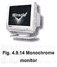
1. Monochrome monitors
•
They display only one color such as green, amber or white against a contrasting
back‒ground which is usually black. They are usually used when colors have no
importance. For example, displaying only text.
2. Grayscale monitors
•
These monitors display various shades of gray, i.e. from a very light gray to
black against a white or off white background. They are especially used in
handheld computers or low‒end portable systems so as to keep costs down.
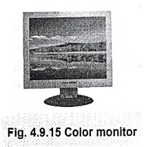
3. Color monitors
•
They can display different colors. The different types of color monitors
display different number of colors ranging from 16 to 16 million colors. Also,
they can be set to operate in monochrome or grayscale mode.
CRT Monitors
The
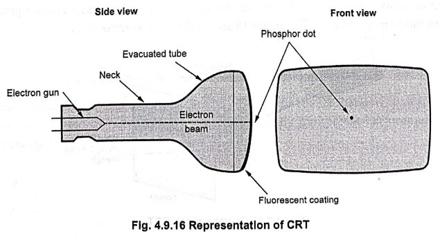
CRT monitor uses a large vacuum tube, called Cathode Ray Tube (CRT). The
working of this CRT is shown in Fig. 4.9.16.
•
A CRT is an evacuated glass tube. An electron gun at the rear of the tube
produces a beam of electrons passes through a magnetic coil called 'yoke' and
is directed towards the front of the tube or screen. The inner side of the
screen is coated with phosphor substance which gives off light when it is
stroked by electrons. The screen's phosphor coating is arranged into a grid of
dots. The smallest number of phosphor dots that the gun can focus on is called
a 'pixel'. Each pixel has a unique address. The computer can locate the pixel
and control its appearance with this address.
•
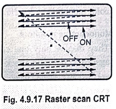
Raster scan is the most common method of displaying images on the CRT screen.
In this method, the horizontal and vertical deflection signals are generated to
move the beam all over the screen as shown in Fig. 4.9.17.
•
Here, the beam is swept back and forth from the left to the right across the
screen. When the beam is moved from the left to the right, it is ON. The beam
is OFF, when it is moved from the right to the left as shown by dotted lines in
Fig. 4.9.17.
•
When the beam reaches the bottom of the screen, it is made OFF and rapidly
retraced back to the top left to start again. This scanning process is similar
to reading different lines on the page of a book. During scanning, the monitor‒driving
circuitry adjusts the intensity of each beam. In a monochrome monitor, this
intensity determines whether a pixel is ON (white) or OFF (black). In a gray
scale monitor, this intensity determines the brightness of each pixel.
Color CRT Monitors
•
A CRT monitor displays color pictures by using a combination of phosphors that
emit different‒coloured light. It generates a range of colors by combining the
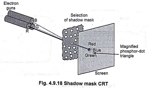
emitted light from the different phosphors. 'Shadow‒mask' is the commonly used
technique in raster‒scan displays including color TV. In a shadow mask
technique, CRT has three phosphor color dots at each pixel position. One
phosphor dot emits a red light, another emits a green light and the third emits
a blue light. Fig. 4.9.18 shows the shadow mask CRT.
•
The shadow mask CRT has three electron guns, one for each color dot and a
shadow mask grid just behind the phosphor coated screen. The shadow mask grid
consists of series of holes aligned with the phosphor dot pattern. Three electron
beams are reflected and focused as a group onto the shadow mask and when they
pass through a hole in the shadow mask, they excite a dot triangle. A dot
triangle consists of three small phosphor dots of red, green and blue color.
These phosphor dots are arranged so that each electron beam can activate only
its corresponding color dot when it passes through the shadow mask. A dot
triangle when activated appears as a small dot on the screen which has color of
combination of three small dots in the dot triangle. By varying the intensity
of the three electron beams we can obtain different colors in the shadow mask
CRT.
Size :
A standard CRT monitor may be more than 16 inches deep and weigh about 30
pounds. Now a days significantly thinner and lighter CRT monitors compared to
old‒ fashioned CRT monitors are available.
Power :
CRT monitors require a lot of power to run.
Flat‒Panel Monitors
•
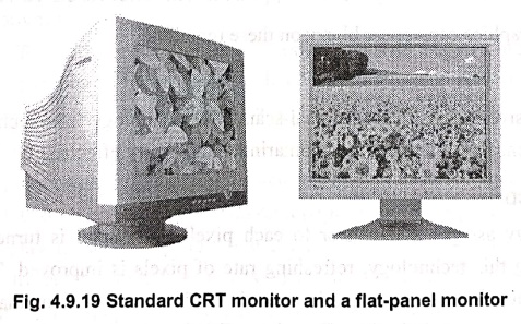
Flat‒panel monitors are very popular among users of desktop systems. The
viewable area of both, CRT monitors and flat‒panel monitors is same, but the
CRT monitors take more space than the flat‒panel monitors. Fig. 4.9.19 shows
this difference.
•
Liquid Crystal Display (LCD) is the common type of flat‒panel monitor. It
creates images with a special kind of liquid crystal, which is normally
transparent but becomes opaque when charged with electricity.
Disadvantages of LCD
monitors
•
It is difficult to see images on it in bright light.
•
The viewing angle of LCD monitor is limited.
With
the improvements in the technology, the viewing angle of flat‒panel monitors is
extended.
There
are two main types of liquid crystal displays, passive matrix LCD and active
matrix LCD.
1. Passive Matrix LCD
They
use transistors for each row and each column of pixels. This creates a grid to
locate each pixel. The electricity coming from the transistors at the end of
the row and the top of the column determines the color displayed by a pixel.
These monitors are inexpensive to manufacture.
Disadvantages
•
They have a narrow viewing angle.
•
Refreshing rate of pixels is less.
•
The quick movement of the pointer disappears it. This effect is called
'submarining'.
•
Animated graphics can appear blurry on these monitors.
Advancement
Now
most passive matrix LCDs use dual‒scan LCD technology. This technology scans
the pixels twice as often. It also reduces the submarining and blurry effects.
2. Active Matrix LCD
This
technology assigns a transistor to each pixel. Each pixel is turned ON and OFF
individually. Using this technology, refreshing rate of pixels is improved. The
submarining effect is not present. The viewing angle is wider in active matrix
screens than passive matrix screens. These displays use Thin‒Film Transistor
(TFT) technology, which uses as many as four transistors per pixel. Now a days
most notebook computers use TFT displays.
Comparison of Standard CRT Monitors with Flat‒Panel Monitors
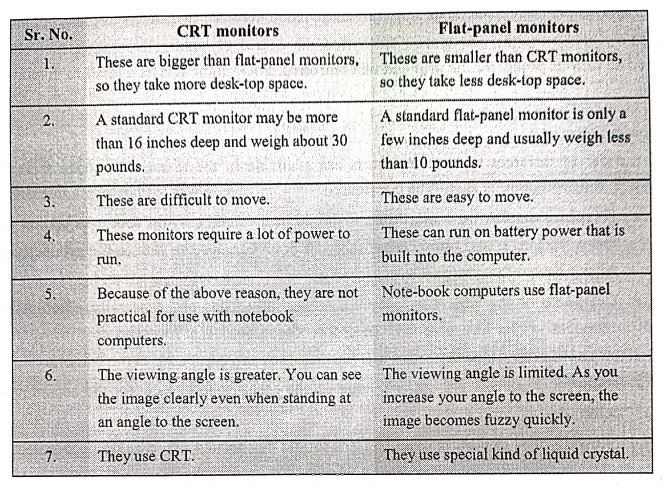
CRT monitors
1. These are bigger than flat‒panel monitors, so
they take more desk‒top space.
2.
A standard CRT monitor may be more than 16 inches deep and weigh about 30
pounds.
3.
These are difficult to move.
4.
These monitors require a lot of power to run.
5.
Because of the above reason, they are not practical for use with notebook
computers.
6.
The viewing angle is greater. You can see the image clearly even when standing
at an angle to the screen.
7.
They use CRT.
Flat‒panel
monitors
1.
These are smaller than CRT monitors, so they take less desk‒top space.
2.
A standard flat‒panel monitor is only a few inches deep and usually weigh less
than 10 pounds.
3.
These are easy to move.
4.
These can run on battery power that is built into the computer.
5.
Note‒book computers use flat‒panel monitors.
6.
The viewing angle is limited. As you increase your angle to the screen, the
image becomes fuzzy quickly.
7.
They use special kind of liquid crystal.
Other Types of Monitors
•
In addition to CRT and flat‒panel monitors, other types of displays are also
used in PC systems. Their operation is based on specialized technology and they
are used in specific applications. Some of them are discussed below.
• Paper‒white displays
These
displays can create high‒quality printed documents. Usually the display on
monitor is such that a black text or graphics is created on a paper‒white
background. An LCD version of paper‒white display is called a 'page‒white
display'. It is based on a special technology, called supertwist to create
higher contrasts. The document designers such as desktop publishing
specialists, newspaper or magazine compositors and the persons who create high
quality printed documents use the paper‒white displays.
•
Electro‒Luminescent Displays (ELDs)
These
displays use a phosphorescent film. This film is held between two sheets of
glass. An image is created by sending current through this film using a grid of
wires.
•
Plasma displays
A
special gas, such as neon or xenon is sandwiched between two sheets of glass in
plasma displays. This gas glows when it is electrified via a grid of small
electrodes. The voltage applied at various points on the grid can be
controlled. Each point acts as a pixel to display an image.
Comparing Monitors
•
A number of different types of monitors are available in the market. To make a
correct choice, following points should be considered
■ Graphics display on a
monitor : It should be nice and easy on your eyes so that you
can work longer and more comfortably. A poor monitor can reduce the
productivity. Also it causes the strain on eyes.
■ Crispness of the
letters : Observe a screen full of text and especially,
examine the crispness of the letters at the corners of the screen. The low‒cost
and low‒quality monitors cause some distortion around the edges and especially
in the corners.
■ Colors :
Observe the familiar picture on the monitor and check for the accuracy of
colors.
The
following most important specifications should be checked while buying a monitor
•
Size
•
Resolution
•
Refresh rate
•
Dot pitch
size
•
The size of the monitor is measured diagonally, across the front of the screen,
in inches. For example, 18 inch monitor means 18 inches from the lower left
corner to the upper right corner. In case of CRT monitor, the viewing area is
less than the size of the monitor. The viewing area of flat‒panel display is
larger than that of same‒sized CRT monitor. As the size of the monitor
increases, the objects on the screen appear bigger, more of them can be viewed
simultaneously and you can see them well.
Resolution
•
The sharpness or clarity of an image is called 'resolution'. In case of
monitor, the number of pixels on the screen determine the resolution of it. It
is expressed as a matrix. As the number of pixels increase, the resolution increases
and the image becomes cleaner and smaller. However, the eyestrain and squinting
problems increase with higher resolution. For example, 640 × 480 resolution
means, there are 640 pixels horizontally across the screen and 480 pixels
vertically down the screen. The actual resolution is determined by the video controller
and not by the monitor itself. Most monitors can be operated at several
different resolutions. The five commonly used resolution settings are,
640
× 480, 800 × 600, 1024 × 768, 1152 × 864 and 1280 × 1024.
The
different standards for monitor resolution are available.
•
Video Graphics Array (VGA)
This
standard is 640 × 480 pixels.
•
Super VGA
This
standard is 800 × 600 and 1024 × 768.
Refresh Rate
•
The electron gun scans every pixel on the screen at the rate called 'refresh
rate'. It is given by the number of times per second. The phosphor dots fade
quickly after the electron gun charges them with electrons. Refreshing is
essential and refresh rate is important. If the screen is not refreshed often
enough, the flicker occurs and it causes an eyestrain. Refresh rate is measured
in Hertz (Hz), i.e. cycles per second. For example, refresh rate is 100 Hz
means it refreshes its pixels 100 times every second. The refresh rate should
be 72 Hz or higher. It should be adequate for the resolution you will be using.
Some monitors have different refresh rates for different resolutions.
Dot Pitch
•
The distance between the similar colored phosphor dots of adjacent pixels, is
called 'dot pitch'. It is the specification of a color monitor. It is measured
as a fraction of a millimeter (mm). It ranges from 0.15 mm which is very fine
to 0.40 mm or higher which is coarse. As the dot pitch decreases, the image
appears finer and more detailed on monitor.
•
The dot pitch should not be greater than 0.28 mm for a 15 inch monitor. For a
larger monitor, it should be 0.22 mm or less.
2. Printers
•
Printers can be classified according to their printing methodology: Impact printers and Non‒impact printers. Impact printers
press formed character faces against an inked ribbon onto the paper. A line
printer and dot matrix printer are the examples of an impact printers. Non
impact printers and plotters use laser techniques, ink‒jet sprays, xerographic
processes, electrostatic methods, and electro‒thermal methods to get images
onto the paper. A ink‒jet printer and laser printer are the examples of non‒impact
printers.
Line Printers
•
A line printer prints a complete line at a time. The printing speed of line
printer vary from 150 lines to 2500 lines per minute with 96 to 100 characters
on one line. The line printers are divided into two categories: Drum printers
and chain printer.
Drum Printers
•
A drum printers consists of a cylindrical drum. One complete set of characters
is embossed on all the print positions on a line, as shown in Fig. 4.9.20. The
character to be printed is adjusted by rotating drum.

•
The codes of all characters to be printed on line are transmitted from the
memory of the computer to a printer memory, commonly known as printer buffer.
This printer buffer can store 132
characters. A print drum is rotated with high speed and when printer buffer
information matches with the drum character, character is printed by striking
the hammer. Thus to print one line drum has to rotate one full rotation. A
carbon ribbon and paper are in between the hammer and the drum therefore when
hammer strikes the paper an impression is made on the backside of the paper by
the ribbon mounted behind the paper. In drum printers to get good impression of
the line on paper it is necessary to synchronize the movements of drum and the
hammer.
Chain Printers
•
In these printers chain with embossed character set is used, instead of drum.
Here, the character to be printed is adjusted by rotating chain. To print line,
computer loads the code of all characters to be printed on line into print
buffer. The chain rotated and when character specified in the print buffer
appears in front of hammer, hammer strikes the carbon ribbon. A carbon ribbon
is placed between the chain, paper and hammer. In this printer to get good
printing quality the movement of hammer and chain must be synchronized.
Dot Matrix Printers
•
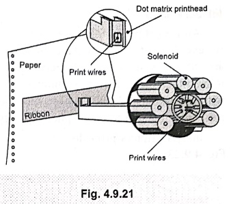
Dot matrix printers are also called serial
printers as they print one character at a time, with printing head moving
across a line. In dot matrix printer the print head consists of a 9 x 7 array
of pins. As per the character definition pin are moved forward to form a
character and they hit the carbon ribbon in front of the paper thereby printing
that character, as shown in Fig. 4.9.21.
•
In these printers character definition can be changed to get different font as shown in Fig. 4.9.22.
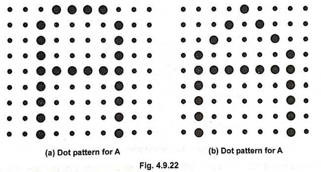
• An other advantage of dot matrix printers is that they can print alphabets other than English, such as Devangari, Tamil etc.
Comparison between line printer and dot matrix printer
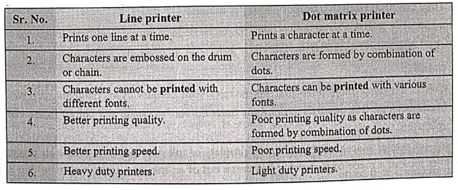
Line printer
1.
Prints one line at a time.
2.
Characters are embossed on the drum or chain.
3.
Characters cannot be printed with different fonts.
4.
Better printing quality.
5.
Better printing speed.
6.
Heavy duty printers.
Dot matrix printer
1.
Prints a character at a time.
2.
Characters are formed by combination of dots.
3.
Characters can be printed with various fonts.
4.
Poor printing quality as characters are formed by combination of dots.
5.
Poor printing speed.
6.
Light duty printers.
Ink‒Jet Printer
An
ink‒jet printer places extremely small droplets of ink onto paper to create an
image. If we ever look at a piece of paper that has come out of an ink‒jet
printer, we know that: the dots are extremely small (usually between 50 and 60
microns in diameter), so small that they are thinner than the diameter of a
human hair (70 microns). The dots are positioned very precisely, with
resolutions of upto 1440 × 720 dots per inch (dpi). The dots can have different
colours combined together to create photo‒quality images.
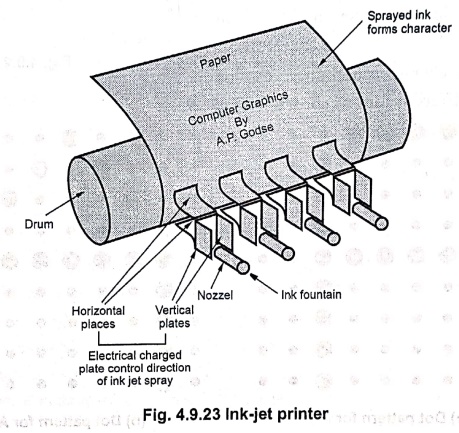
Ink
jet printers print directly on paper by spraying ink through tiny nozzles as
shown in Fig. 4.9.23.
•
As shown in Fig. 4.9.23, the ink is deflected by an electric field with the
help of horizontal and vertical charged plates to produce dot matrix
Features of ink‒jet printer
1.
They can print from two to four pages per minute.
2.
Resolution is about 360 dots per inch, therefore better printing quality is
achieved.
3.
The operating cost is quite low, the only part that needs replacement is the
ink cartridge.
4.
Colour ink‒jet printers have four ink nozzles with colours cyan, magenta,
yellow and black, because it is possible to combine these colours to create any
colour in the visible spectrum.
•
An ink‒jet printer places extremely small droplets of ink onto paper to create
an image. If we ever look at a piece of paper that has come out of an ink‒jet
printer, we know that: the dots are extremely small (usually between 50 and 60
microns in diameter), so small that they are thinner than the diameter of a
human hair (70 microns). The dots are positioned very precisely, with
resolutions of up to 1440 × 720 dots per inch (dpi). The dots can have
different colours combined together to create photo‒quality images. Ink‒jet
printers print directly on paper by spraying ink through tiny nozzles.
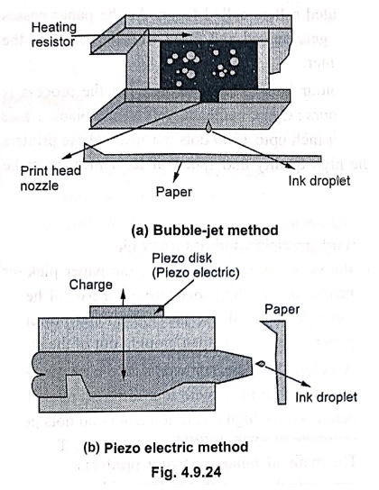
•
An ink‒jet printer has a print cartridge with a series of tiny electrically
heated chambers. These cartridges are attached to print heads with a series of
small nozzles that spray ink onto the surface of the paper. As print head moves
back and forth across the page, the software tells the position where the dots
of ink should be 'sprayed'. It also gives instructions regarding the type and the
quantity of colours. There are two main ways to drop the ink droplets, namely,
the bubble‒jet and piezo‒electric technology. Bubble‒jet
printers use heat to fire ink onto the paper. There are three main stages with
this method.
•
Initially the bubble is created by heating the ink.
•
The pressure force is applied to burst and then hit the bubble on the paper.
•
The bubble then collapses as the element cools and the resulted vacuum in the
nozzle draws ink from the reservoir to replace the ink that was ejected.
•
In the piezo‒electric method, piezo crystal is used and it is located at the
back of ink reservoir. When electric current flows through the piezo crystal,
it contracts and thus forces a drop of ink out of the nozzle.
Laser Printers
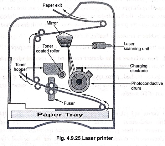
•
The line, dot matrix and ink‒jet printers need a head movement on a ribbon to
print characters. This mechanical movement is relatively slow due to the high
inertia of mechanical elements. In laser printers these mechanical movements
are avoided. In these printers, an electronically controlled laser beam traces
out the desired character to be printed on a photoconductive drum. The exposed
areas of the drum gets charged, which attracts an oppositely charged ink from
the ink toner on to the exposed areas. This image is by then transferred to the
paper when it comes in contact with the drum with pressure applied by the
pressure roller. The charge on the drum decides the darkness of the print. When
the charge is more, more ink is attracted and we get a dark print.
•
This pressure roller transfers the black toner onto the paper. Since the paper
is moving at the same speed as the drum, the paper picks up the image pattern
precisely. Finally, the printer passes the paper through a pair of heated
rollers called fuser. As the paper
passes through these rollers. The loose toner power gets melted and fuses with
the fibres in the paper. The paper is then brought out of the printer.
•
A colour laser printer works like a single colour laser printer, except that
the process is repeated four times with four different ink colours : Cyan,
magenta, yellow and black. Laser printers have high resolution from 600 dots
per inch upto 1200 dots per inch. These printers print 4 to 16 page of text per
minute. The high quality and speed of laser printers make them ideal for office
environment.
Advantages of Laser printer
•
The main advantages of laser printers are speed, precision and economy. A laser
can move very quickly, so it can "write" with much greater speed than
an ink‒jet. Because the laser beam has an unvarying diameter, it can draw more
precisely, without spilling any excess ink. Laser printers tend to be more
expensive than ink‒jet printers, but it doesn't cost as much to keep them
running. Its toner power is cheap and lasts for longer time.
Thermal Transfer Printer
•
In thermal transfer printer, wax paper and plain paper are drawn together over
the strip of heating nibs. The heating nibs are selectively heated to cause the
pigment transfer.
•
In case of colour thermal transfer printers, the wax paper is placed on a roll
of alternating, cyan, magenta, yellow and black strips, each of a length equal
to the paper size. It is possible to create one colour hardcopy with less than
1 minute. This is possible because the material used to manufacture nib heats
and cools very rapidly. Modern thermal transfer printers accept a video signal
and digital bitmap input, making them convenient for creating hardcopy of video
images.
Review Questions
1. Write a short note
on
a) Keyboard
b) Mouse
c) Scanner
2. Write a short note
on
a) Cathode‒Ray Tubes
b) Vector scan display
c) Raster scan display
d) Beam penetration
technique
e) Shadow mask
technique
3. Explain the working
of direct‒view storage tubes.
4. List the advantages
and disadvantages of DVST.
5. Write a short note
on
a) Flat panel display
b) Plasma panel display
6. List the important
characteristics of video display devices.
7. Write a short note
on dot matrix printer.
8. Write a short note
on desk jet printer.
9. Write a short note
on laser printer.
10. Write short notes
on I/O devices.
Computer Organization and Architecture: Chapter 4: Memory and IO : Tag: Computer : - Peripheral Input and Output Devices
Computer Organization and Architecture: Chapter 4: Memory and IO
Under Subject
Computer Organization and Architecture
CW25201 3rd Semester IT department. | 2025 Regulation | 3rd Semester 2025 Regulation
Related Subjects
Discrete Mathematics
MA25C14 3rd Semester CSE,IT,CY,AIDS departments. | 2025 Regulation | 3rd Semester 2025 Regulation
Data Structures
CS25C08 3rd Semester CSE,IT,CY,AIDS departments. | 2025 Regulation | 3rd Semester 2025 Regulation
Computer Organization and Architecture
CW25201 3rd Semester IT department. | 2025 Regulation | 3rd Semester 2025 Regulation
Object Oriented Programming
CS25C07 3rd Semester IT department. | 2025 Regulation | 3rd Semester 2025 Regulation
Web Technologies
IT25301 3rd Semester IT department. | 2025 Regulation | 3rd Semester 2025 Regulation
English Communication Skills Laboratory I
EN25C03 3rd Semester all department. | 2025 Regulation | 3rd Semester 2025 Regulation
Skill Development Course I
3rd Semester all department. | 2025 Regulation | 3rd Semester 2025 Regulation