Computer Organization and Architecture: Chapter 4: Memory and IO
Virtual Memory
Questions: 1. What is virtual memory? 2. What are benefits of virtual memory? 3. Explain the virtual memory address translation and TLB with necessary diagram. 4. What is virtual memory? Explain how the logical address is translated into physical address in the virtual memory system with a neat diagram. 5. Discuss the address translation mechanism. 6. What is the function of a TLB (Translation Look‒aside Buffer)? 7. Define Translation Lookaside Buffer (TLB}. What is its use? 8. Explain a method translating virtual address to physical address. 9. Write short note on page segmentation. 10. Write a short note on demand paging. 11. What are the page replacement algorithms? Give details of LRU algorithm. 12. What are the steps involved in LRU replacement algorithm? 13. What is virtual memory? Explain in detail about how virtual memory is implemented with neat diagram? 14. Discuss the steps involved in the address translation of virtual memory with necessary block diagram. 15. Explain virtual memory address translation in detail with necessary diagrams.
Virtual
Memory
•
Virtual memory is a technique that allows programs to use more memory than what
is physically available by temporarily transferring data between main memory
(RAM) and secondary storage (disk).
•
When a program does not completely fit into the main memory, it is divided into
segments. The segments which are currently being executed are kept in the main
memory and remaining segments are stored in the secondary storage devices, such
as a magnetic disk.
•
If an executing program needs a segment which is not currently in the main
memory, the required segment is copied from the secondary storage device. When
a new segment of a program is to be copied into a main memory, it must replace
another segment already in the memory.
•
In virtual memory, the addresses that processor issues to access either
instruction or data are called virtual
address. The set of such addresses is called address space.
•
These addresses are translated into physical addresses by a combination of
hardware and software components. The set of physical addresses or locations is
called the memory space.
1. Paging and Segmentation
•
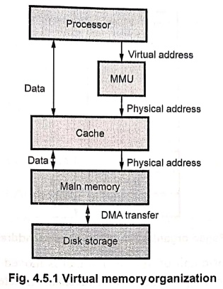
Fig. 4.5.1 shows a typical memory organization that implements virtual memory.
The Memory Management Unit (MMU) performs
the translation between virtual
addresses (used by programs) and physical
addresses (used by hardware).
•
Two important techniques used in virtual memory management are :
■ Segmentation
■ Paging
1. Segmentation
•
Segmentation divides a program's memory into variable‒sized logical segments
such as code, data, stack, etc. Each
segment represents a logical unit of a program.
•
A virtual address consists of two parts:
1. Segment number
(selector)
2. Offset (within that
segment)
•
The segment number points to an entry in the segment table, which contains:
1. Base address
of the segment in memory
2. Limit (length)
of the segment
•
The base address is added to the offset to obtain the linear address.
•
If paging is not used, the linear address becomes the physical address.
2. Paging
•
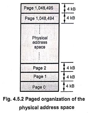
Paging divides both physical and virtual memory into fixed‒size blocks‒pages (in virtual memory) and frames (in physical memory). Fig. 4.5.2
shows paged organization of the physical address space.
•
Pages constitute the basic unit of information that is moved between the main
memory and the disk whenever the page translation mechanism determines that a
swapping is required.
•
A virtual address consists of:
■
Page number
■
Page offset
•
The Page Table Base Register (PTBR)
holds the starting address of the page table. The page number is used as an index into the page table to obtain the frame number. The frame number is concatenated with the offset to form the physical
address.
3. Combined paging and segmentation
•
Many systems (like Intel x 86) use both
segmentation and paging together.
■ Segmentation
provides logical organization of a program.
■ Paging
efficiently manages physical memory allocation.
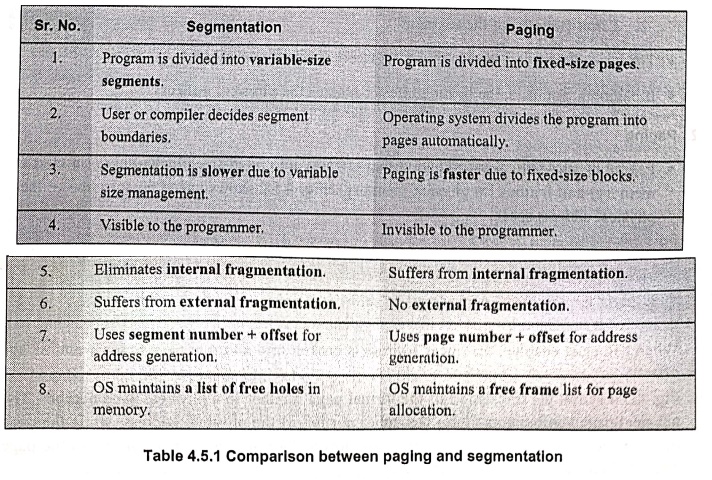
Comparison between Paging and Segmentation
Segmentation
1.
Program is divided into variable‒size
segments.
2.
User or compiler decides segment boundaries.
3.
Segmentation is slower due to variable size management.
4.
Visible to the programmer.
5.
Suffers from internal fragmentation.
6.
No external fragmentation.
7.
Uses page number + offset for address
generation.
8.
OS maintains a free frame list for
page allocation.
Paging
1.
Program is divided into fixed‒size
pages.
2.
Operating system divides the program into pages automatically.
3.
Paging is faster due to fixed‒size blocks.
4.
Invisible to the programmer.
5.
Eliminates internal fragmentation.
6.
Suffers from external fragmentation.
7.
Uses segment number + offset for
address generation.
8.
OS maintains a list of free holes in
memory.
2. Virtual to Physical Address Translation
•
When both segmentation and paging are used together (as in modern processors
like Intel x86) address translation Involves two phases:
1. Segment translation :
Converts logical address (segment + offset) into a linear address.
2. Page translation :
Converts the linear address into a physical
address using a page table.
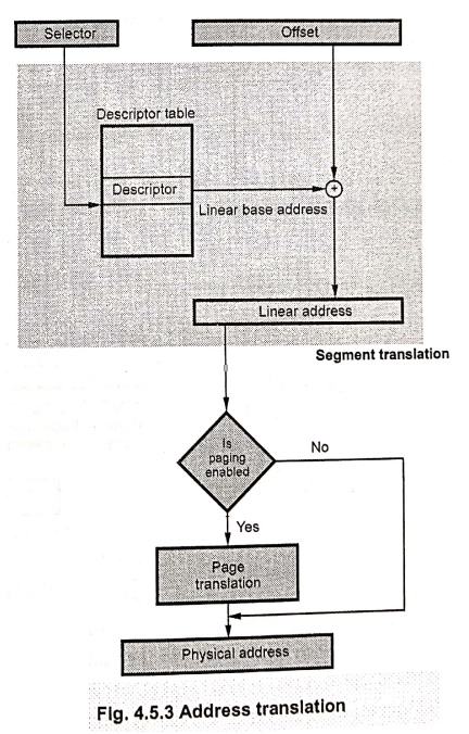
Segment translation:
•
A logical address (also known as virtual address) consists of a selector and an
offset. A selector is the contents of a segment register.
•
Every segment selector has a linear base address associated with it and it is
stored in the segment descriptor. A selector is used to point a descriptor for
the segment in a table of descriptors. The linear base address from the
descriptor is then added to the offset to generate the linear address. This process is known as segmentation or segment
translation. If paging unit is not enabled then the linear address
corresponds to the physical address. But if paging unit is enabled, paging
mechanism translates the linear address space into the physical address space
by paging translation.
Page translation
•
Page translation is the second phase of address translation. It transforms a
linear address generated by segment translation into a physical address.
•
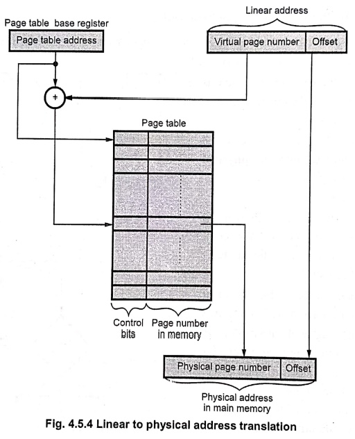
When paging is enabled, the linear address is broken into a virtual page number
and a page offset.
•
Fig. 4.5.4 shows the translation of the virtual page number to a physical page
number. The physical page number constitutes the upper portion of the physical
address, while the page offset, which is not changed, constitutes the lower
portion. The number of bits in the page offset field decides the page size.
•
The page table is used to keep the
information about the main memory location of each page. This information
includes the main memory address where the page is stored and the current
status of the page.
•
To obtain the address of the corresponding entry in the page table the virtual
page number is added with the contents of page table base register, in which
the starting address of the page table is stored. The entry in the page table
gives the physical page number, in which offset is added to get the physical
address of the main memory.
Example :
1
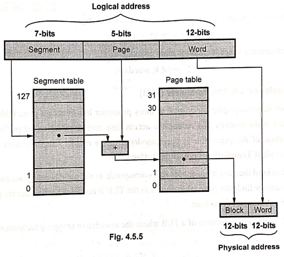
The logical address
space in a computer system consists of 128 segments. Each segment can have up
to 32 pages of 4 K words each. Physical memory consists of 4 K blocks of 4 K
words in each. Formulate the logical and physical address formats.
Solution :
Number
of bits for segment address = log2 128 = log2 27
= 7 bits
Number
of bits for page address = log2 32 = log2 25 =
5 bits
Number
of bits for word address = log2 4096 = log2 212
= 12 bits
Number
of bits for block address = log2 4096 = log2 212
= 12 bits
Example :
2
An address space is
specified by 32 bits and corresponding memory space by 24 bits.
i) How many words are
there in the address space?
ii) How many words are
there in the memory space?
iii) If a page consists
of 4 K words, how many pages and blocks are there in the systems.
Solution :
i)
Words in the address space = 232
= 4 G words
ii)
Words in the memory space = 224
= 16 M words
iii)
Number of pages = Words in address space / Words per page = 4 G words / 4 K
words
= 1 M pages
iv)
Number of blocks = Words in address space / (Words per page/block)
= 16 M words / 4 K blocks = 4 K words
Example :
3
An address space is
specified by 24 bits and the corresponding memory space by 16 bits. How many
words are there in the virtual memory and in the main memory?
Solution :
Words
in the address space, i.e., in the virtual memory
= 224=
16 M words
Words
in the memory space, i.e., in the main memory
=224
= 64 K words
3. Translation Lookaside Buffer (TLB)
•
To support demand paging and virtual memory processor has to access page table
which is kept in the main memory. To reduce the access time and degradation of
performance, a small portion of the page table is accommodated in the memory
management unit. This portion is called Translation
Lookaside Buffer (TLB).
•
It is used to hold the page table entries that corresponds to the most recently
accessed pages. When processor finds the page table entries in the TLB it does
not have to access page table and saves substantial access time.
•
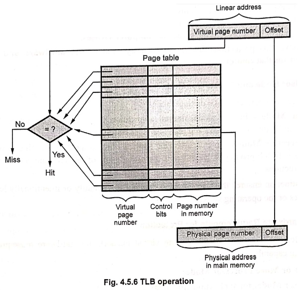
Fig. 4.5.6 shows a organization of a TLB where the associative mapping
technique is used.
•
As shown in Fig. 4.5.6, a given virtual address is compared with the TLB
entries for the reference page by MMU. If the page table entry for this page is
found in the TLB, the physical address is obtained immediately.
•
If entry is not found, there is a miss in
the TLB, then the required entry is obtained from the page table in the main
memory and the TLB is updated.
•
It is important that the contents of the TLB be coherent with the contents of
page tables in the memory. When page table entries are changed by an operating
system, it must invalidate the corresponding entries in the TLB. One of the
control bits in the TLB is provided for this purpose. When an entry is
invalidated, the TLB acquires the new information as a part of the MMU's normal
response to access misses.
4. Implementing Protection with Virtual Memory
1. Need for Protection
•
The most important function of virtual
memory in modern computer systems is to allow multiple processes to share the same main memory safely. Each process must be protected so that it
cannot read or modify the memory contents of another process or the operating system.
•
Without proper protection, one faulty or malicious program could overwrite data
belonging to another process or the operating system, causing system crashes or
data leaks. Such protection also helps prevent the spread of computer viruses.
To achieve this protection, the virtual memory system uses hardware and software mechanisms that control access to memory.
2. User Mode and Supervisor Mode
•
The processor operates in two distinct modes:
1. User Mode ‒
In this mode, normal application programs are executed. Access to certain
hardware resources and instructions is restricted.
2. Supervisor Mode
(also called Kernel Mode) ‒ In this mode, operating system code runs with full privileges. It can access
protected parts of memory and special processor instructions.
•
This distinction ensures that user programs cannot accidentally or
intentionally harm other processes or the operating system.
3. Hardware Requirements for Protection
•
To implement memory protection using virtual memory, the hardware must provide
the following capabilities:
1. Two or More Processor Modes
■
User Mode (for application programs)
♦
Supervisor Mode (for operating
system functions)
These
modes determine what instructions and memory regions a process can access.
2. Protected Processor State
■
Certain parts of the processor state must be readable but not writable by user programs.
■
This includes:
♦ The
user/supervisor mode bit, which indicates the current mode.
♦ The page
table pointer, which defines the current address mapping.
♦ The Translation
Lookaside Buffer (TLB), which stores recent address translations.
■
Only the operating system can modify these using special instructions available in supervisor mode.
3. Mechanism for Mode Switching
■
The processor must provide a way to switch from
user mode to supervisor mode and back. This transition is essential when a
program needs an operating system service.
■
The switch from user to supervisor mode happens through a system call, which is a special instruction (for example, ecall in RISC‒V).
■
When a system call is made:
♦ Control is transferred to a predefined
location in the operating system code.
♦ The processor saves the current Program
Counter (PC) in a special register called Supervisor
Exception Program Counter (SEPC).
♦ The processor enters supervisor mode.
■ To return to user mode, the instruction sret (supervisor return) is executed. It restores the previous PC from SEPC and switches the processor back to user mode.
4. Protecting the Page Tables
•
In a virtual memory system, each process has its own page table that maps its virtual addresses to physical memory
addresses. To ensure protection:
■ User processes cannot
modify their page tables.
■ The operating system
maintains and modifies page tables, as they are stored in a protected area of memory (accessible
only in supervisor mode).
•
This ensures that a user program cannot access or modify another program's
memory by changing its own mappings.
• Each process therefore operates in its own virtual address space. The operating system ensures that these address spaces map to disjoint physical memory areas, so that one process cannot read or write data belonging to another.
5. Controlled Sharing of Memory
•
Sometimes, two processes may need to share data (for example, a shared file or
a communication buffer). In such cases, the operating system assists by modifying the page tables
appropriately. For example, suppose process P1 wants to share a page with process P2.
■
P2 requests the operating system to
create an entry in its page table that points to the same physical page used by
P1.
■
The operating system can use the write
protection bit to control access.
♦ If read‒only sharing is required, the write
bit is cleared so P2 can only read but not modify the shared page.
♦ If full access is allowed, both processes can read and write.
6. Role of the TLB in Protection
•
The Translation Lookaside Buffer (TLB)
is a small cache in the processor that stores recent virtual‒to‒physical
address translations along with protection
bits.
•
These bits include:
■
Read/Write permission bit
■
Valid / Invalid bit
■
Access rights (user/supervisor)
•
Since the page table is accessed
only when a TLB miss occurs, the same protection information must be stored in
the TLB to ensure every memory
access obeys protection rules.
5. Page Size
•
The page size has a great effect on both storage utilization and the effective
memory data transfer rate. It is denoted by Sp.
•
If Sp is too large, excessive internal fragmentation results and if
it is too small, the page tables become very large. This tends to reduce space
utilization (u). There should be balance between these two schemes.
•
Let us denote the average segment size in words as S,. If Ss
>> Sp, the last page assigned to ma segment should contain
about Sp / 2 words. The size of the page table associated with each
segment is approximately Ss / Sp words, assuming each
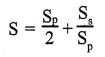
entry in the table is a word. Hence the memory space overhead associated with
each segment is,
S
= (Sp / 2) + (Ss / Sp)
•
The space utilization factor u is given as,
u
= Ss / [Ss+S] = [ Ss / [Ss +( Sp/2)
+ (Ss / Sp ) ]
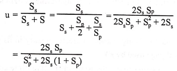
=
2Ss Sp / [S2p+2Ss (1 + Sp)]
•
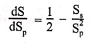
We can derive the expression for optimum page size SOPTp
by defining the value of Sp, that maximizes u or, equivalently, that
minimizes S. Differentiating S with respect to we obtain
dS / dSP =1/2 – Ss/S2p
•
Now equating dS / dSP to 0 we have,
0 =1/2 – Ss/S2p
•
S is minimum when dS / dSP = 0
SOPTP = √ (2Ss)
•
Substituting the value of SOPTP in equation (4.5.2), we
get the optimum space utilization as,
uОРТ = 2Ss√(2Ss) / [(√(2Ss))2 +2Ss(
1+√(2Ss))] = 2Ss√(2Ss)
/ [ 4Ss +2Ss(√(2Ss))2 ]
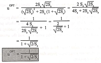
= 1 / [ 4Ss / 2Ss√2Ss
+ ̧1 ] = 1 / ( 2/√2Ss + ̧1)
= 1 / (1+
√(2/Ss) )
uОРТ =
1 / (1+ √(2/Ss) )
•
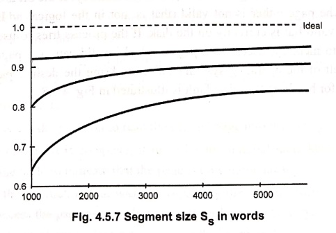
Fig. 4.5.7 shows the effect of page size and segment size on space utilization.
It shows that space utilization factor increases with increase in segment size
and it is optimum when Sp = √
2Ss
6. Page Fault and Demand Paging
•
If the page required by the processor is not in the main memory, the page fault occurs and the required page
is loaded into the main memory from the secondary storage memory by special
routine called page fault routine.
•
This technique of getting the desired page in the main memory is called demand paging.
•
A demand ‒ paging system is similar to a paging system with swapping. A swapper
never swaps a page into memory unless that page is needed. Since we are now
viewing a program as a sequence of pages, rather than one large contiguous
address space, the use of the term swap is technically incorrect. A swapper
manipulates entire programs, whereas a pager is concerned with the individual
pages of a program. Hence term pager is usually used, rather than swapper, in
connections with demand paging.
•
When a program is to be swapped in, the pager guesses which pages will be used
before the program is swapped out again. Instead of swapping in a whole
process, the pager brings only those necessary pages into memory. Thus, it
avoids reading into memory pages that will not be used any way, decreasing the
swap time and the amount of physical memory needed.
•
With this scheme, we need some form of hardware support to distinguish between
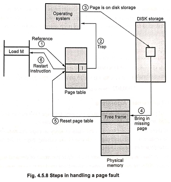
those pages that are in memory and those pages that are on the disk. Fig. 4.5.8
shows hardware to implement demand paging.
•
As shown in Fig. 4.5.8, the valid‒invalid bits are used to distinguish between
those pages that are in memory and those pages that are on the disk. When bit
is set to "valid", it indicates that the associated page is both
legal and in memory. If the bit is set to "invalid", it indicates that
the page either is not valid (that is, not in the logical address space of the
process), or is valid but is currently on the disk. If the process tries to use
a page that was not brought into memory, access to a page marked invalid causes
a page‒fault trap. This trap is the result of the operating system's failure to
bring the desired page into memory. The procedure for handling this page fault
is illustrated in Fig. 4.5.8.
•
This procedure goes through following steps:
1.
It checks an internal table for this program, to determine whether the
reference was a valid or invalid memory access.
2.
If the reference is invalid, it terminates the process. If it is valid, but the
referenced page is not available in the physical memory, trap is activated.
3.
It finds a free frame.
4.
It schedules a disk operation to read the desired page into the newly allocated
frame.
5.
When the disk read is complete, it modifies the internal table kept with the
program and the page table to indicate that the page is now in memory.
6.
It restarts the instruction that was interrupted by the illegal address trap.
The program can now access the page as though it had always been in memory.
•
The hardware to implement demand paging is the same as the hardware for paging
and swapping :
Page table :
This table has the ability to mark an entry invalid through a valid ‒ invalid
bit or special value of protection bits.
Secondary memory :
This memory holds those pages that are not present in main memory. The
secondary memory is usually a hard disk. It is known as the swap device and the
section of disk used for this purpose is known as swap space or backing store.
Example :
4
Calculate the effective
address time if average page‒fault service time of 20 milliseconds and a memory
access time of 80 nanoseconds. Let us assume the probability of a page fault
10%
Solution :
Effective access time is given as
=
(1 − 0.1) × (80) + 0.1 (20 milliseconds)
=
(1 − 0.1) × 80 + 0.1 × 20,000,000 = 72 + 2,000,000 (nanoseconds)
=
2,000,072 (nanoseconds)
7. Page Replacement Algorithms
•
If the required page is not found in the main memory, the page fault occurs and
the required page is loaded into the main memory from the secondary memory.
•
However, if there is no vacant space in the main memory to copy the required
page, it is necessary to replace the required page with one of the existing
page in the main memory which is currently not in use.
•
Thus we can say that the page replacement is a basic requirement of demand paging.
•
There are many different page ‒ replacement algorithms used by various
operating systems. These are discussed in the following sections.
FIFO algorithm
•
It is the simplest page‒replacement algorithm. A FIFO (First In First Out)
replacement algorithm replaces the new page with the oldest page in the main
memory.
•
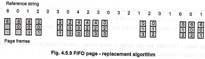
For our example reference string, our three frames are initially empty. The
first three references (6, 0, 1) cause page faults and the required pages are
brought into these empty frames.
The
next reference (2) replaces page 6, because page 6 was brought in first. Since
0 is the next reference and 0 is already in memory, we have no fault for this
reference. The first reference to 3 results in page 0 being replaced, since it
was the first of the three pages in memory (0, 1 and 2) to be brought in. This
process continues as shown in Fig. 4.5.9.
•
The FIFO page‒replacement algorithm is easy to understand and program. However,
its performance is not always good. It may replace the most needed page as it
is oldest page.
Optimal algorithm
• Advantage :
An optimal page‒replacement algorithm has the lowest page ‒ fault rate of all
algorithms. It has been called OPT or MIN.
•
It simply states that "Replace the
page that will not be used for the longest period of time".
•
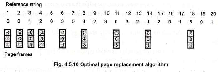
For example, on our sample reference string, the optimal page replacement
algorithm would yield nine page faults, as shown in Fig. 4.5.10. The first
three references cause faults that fill the three empty frames.
•
The reference to page 2 replaces page 6, because 6 will not be used until
reference 18, whereas page 0 will be used at 5 and page 1 at 14. The reference
to page 3 replaces page 1, as page 1 will be the last of the three pages in
memory to be referenced again. With only nine page faults, optimal replacement
is much better than a FIFO algorithm, which had 15 faults. (If we ignore the
first three, which all algorithms must suffer, then optimal replacement is twice
as good as FIFO replacement.) In fact, no replacement algorithm can process
this reference string in three frames with less than nine faults.
• Disadvantage :
Unfortunately, the optimal page replacement algorithm is difficult to
implement, because it requires future knowledge of the reference string.
LRU algorithm
•
The algorithm which replaces the page that has not been used for the longest
period of time is referred to as the Least
Recently Used (LRU) algorithm.
•
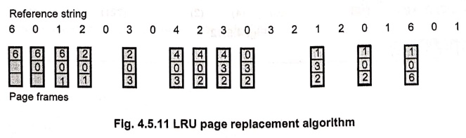
The result of applying LRU replacement to our example reference string is shown
in Fig. 4.5.11.
•
When the reference to page 4 occurs, LRU replacement sees that, of the three
frames in memory, page 2 was used least recently. The most recently used page
is page 0 and just before that page 3 was used. Thus, the LRU algorithm
replaces page 2, not knowing that page 2.
•
When it then faults for page 2, the LRU algorithm replaces page 3 since, of the
three pages in memory {0, 3, 4}, page 3 is the least recently used.
•
LRU replacement with 12 faults is still much better than FIFO replacement with
15.mi
Counting algorithms
•
In the counting algorithm the a counter of the number of references that have
been made to each pages are kept and based on these counts the following two
schemes work.
• LFU algorithm: The
Least Frequently Used (LFU) page replacement algorithm
requires that the page with the smallest count be replaced.
•
The reason for this selection is that an actively used page should have a large
reference count.
•
This algorithm suffers from the situation in which a page is used heavily
during the initial phase of a process, but then is never used again.
• MFU algorithm: The
Most Frequently Used (MFU) page replacement algorithm is
based on the argument that the page with the smallest count was probably just
brought in and has yet to be used.
Example :
5
Explain page
replacement algorithms. Find out page fault for following string using LRU
method
60 12 0 30 4 2 30 321 20
15
Consider page frame
size = 3.
Solution :
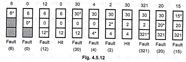
Total
page faults = 09
Example :
6
Explain page
replacement algorithm. Find out page fault for following string using LRU
method. Consider page frame size 3.
7 0 1 2 0 3 0 4 2 3 0 3
2 1 2 0 1 7 0 1.
Solution :
Reference string
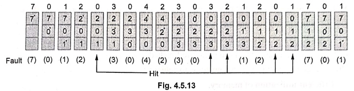
Total
page faults = 15
Review Questions
1. What is virtual
memory?
2. What are benefits
of virtual memory?
3. Explain the virtual
memory address translation and TLB with necessary diagram.
4. What is virtual
memory? Explain how the logical address is translated into physical address in
the virtual memory system with a neat diagram.
5. Discuss the address
translation mechanism.
6. What is the
function of a TLB (Translation Look‒aside Buffer)?
7. Define Translation
Lookaside Buffer (TLB}. What is its use?
8. Explain a method
translating virtual address to physical address.
9. Write short note on
page segmentation.
10. Write a short note
on demand paging.
11. What are the page
replacement algorithms? Give details of LRU algorithm.
12. What are the steps
involved in LRU replacement algorithm?
13. What is virtual
memory? Explain in detail about how virtual memory is implemented with neat
diagram?
14. Discuss the steps
involved in the address translation of virtual memory with necessary block
diagram.
15. Explain virtual
memory address translation in detail with necessary diagrams.
Computer Organization and Architecture: Chapter 4: Memory and IO : Tag: Computer : - Virtual Memory
Computer Organization and Architecture: Chapter 4: Memory and IO
Under Subject
Computer Organization and Architecture
CW25201 3rd Semester IT department. | 2025 Regulation | 3rd Semester 2025 Regulation
Related Subjects
Discrete Mathematics
MA25C14 3rd Semester CSE,IT,CY,AIDS departments. | 2025 Regulation | 3rd Semester 2025 Regulation
Data Structures
CS25C08 3rd Semester CSE,IT,CY,AIDS departments. | 2025 Regulation | 3rd Semester 2025 Regulation
Computer Organization and Architecture
CW25201 3rd Semester IT department. | 2025 Regulation | 3rd Semester 2025 Regulation
Object Oriented Programming
CS25C07 3rd Semester IT department. | 2025 Regulation | 3rd Semester 2025 Regulation
Web Technologies
IT25301 3rd Semester IT department. | 2025 Regulation | 3rd Semester 2025 Regulation
English Communication Skills Laboratory I
EN25C03 3rd Semester all department. | 2025 Regulation | 3rd Semester 2025 Regulation
Skill Development Course I
3rd Semester all department. | 2025 Regulation | 3rd Semester 2025 Regulation