Basic Electronics and Electrical Engineering: Chapter 4: Synchronous Machines
Alternator on Load
Synchronous Machines
As the load on an alternator is varied, its terminal voltage is also found to vary as in DC generators.
ALTERNATOR
ON LOAD
As the load on an
alternator is varied, its terminal voltage is also found to vary as in DC
generators. This variation in terminal voltage V is due to the following three
reasons:
1.
Voltage drop due to armature resistance (Ra)
2.
Voltage drop due to armature leakage reactance (XL)
3.
Voltage drop due to armature reaction.
1. Armature Resistance (Ra)
The armature resistance
/ phase Ra causes a voltage drop/phase of IRa which is in
phase with the armature current I. However, this voltage drop is practically
negligible.
2. Armature leakage reactance (XL)
When current flows
through the armature conductors, fluxes are setup which do not cross the air‒gap,
but take different paths. Such fluxes are known as leakage fluxes.
The leakage flux is
practically independent phase of saturation, but is dependent on I and its
phase angle with terminal voltage V. This leakage flux sets up an emf of self‒inductance
which is known as reactance emf and which is ahead of I by 90°. Hence, armature
winding is assumed to posses leakage reactance XL, such that voltage
drop to this equals IXL.
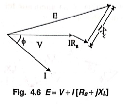
Therefore, E = V + I[Ra
+ jXL]
This is shown in Fig.
4.6.
3. Armature Reaction
The voltage drop due to
armature reaction is accounted for by assuming a fictitious reactance Xa
in the armature winding. The phasor sum of XL and Xa
gives “synchronous reactance" (XS). Hence XS = XL
+ Xa
As in DC generators,
armature reaction is the effect of armature flux on the main field flux. In
case of alternators, the powerfactor of the load has a considerable effect on
the armature reaction.
(i) Unity p.f load
(ii) Lagging p.f load
(iii) Leading p.f load.
We will discuss about
three cases of power factor.
(i) Unity p.f load
Fig. 4.7 shows the
phasor diagram of an alternator for unity p.f. load. Here terminal voltage V is
taken as the reference phasor. The current phasor Ia is in phase
with terminal voltage V. The voltage drop IaRa is in
phase with Ia while the voltage drop IaXs
leads Ia by 90°. The vector sum of two voltage drops gives IaZs.
The vector sum of terminal voltage V and IaZs gives E.

(ii) Lagging p.f load
Fig. 4.8 shows the
phasor diagram of an alternator for lagging p.f load. Here terminal voltage V
is taken as the reference phasor.
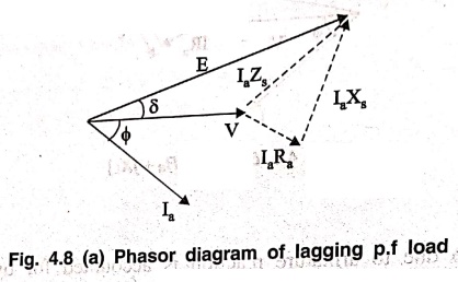
The current Ia
is lagging behind the voltage by ϕ. The IaRa drops is
inphase with Ia while the drop IaXs leads Ia
by 90°, The vector sum of IaRa and IaXs
gives IaZs. Then the vector sum of terminal voltage V and
IaZS gives E.
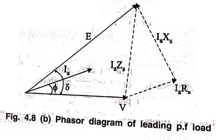
(iii) Leading p.f load
Fig. 4.8 (b) shows the
phasor diagram of an alternator for leading p.f load. Here again V is taken as
the reference phasor. The current Ia leads V by ϕ. The IaRa
drop is inphase with Ia while the drop IaXs
leads Ia by 90°. The vector sum of IaRa and IaXs
gives IaZs Then the vector sum of terminal voltage V and
IaZs gives E.
Basic Electronics and Electrical Engineering: Chapter 4: Synchronous Machines : Tag: Basic Engineering : Synchronous Machines - Alternator on Load
Basic Electronics and Electrical Engineering: Chapter 4: Synchronous Machines
Under Subject

Basic Electronics and Electrical Engineering
EE25C04 1st Semester ECE Dept | 2025 Regulation | 2nd Semester 2025 Regulation
Related Subjects

English Essentials I
EN25C01 1st Semester | 2025 Regulation | 1st Semester 2025 Regulation

தமிழர் மரபு - Heritage of Tamils
UC25H01 1st Semester | 2025 Regulation | 1st Semester 2025 Regulation

Applied Calculus
MA25C01 Maths 1 M1 - 1st Semester | 2025 Regulation | 1st Semester 2025 Regulation

Applied Physics I
PH25C01 1st Semester | 2025 Regulation | 1st Semester 2025 Regulation

Applied Chemistry I
CY25C01 1st Semester | 2025 Regulation | 1st Semester 2025 Regulation

Makerspace
ME25C04 1st Semester | 2025 Regulation | 1st Semester 2025 Regulation

Computer Programming C
CS25C01 1st Semester | 2025 Regulation | 1st Semester 2025 Regulation

Computer Programming Python
CS25C02 1st Semester | 2025 Regulation | 1st Semester 2025 Regulation

Fundamentals of Electrical and Electronics Engineering
EE25C03 1st Semester | 2025 Regulation | 1st Semester 2025 Regulation

Introduction to Mechanical Engineering
ME25C03 1st Semester | 2025 Regulation | 1st Semester 2025 Regulation

Introduction to Civil Engineering
CE25C01 1st Semester Civil Department | 2025 Regulation | 1st Semester 2025 Regulation

Essentials of Computing
CS25C03 1st Semester - AID CSE IT Department | 2025 Regulation | 1st Semester 2025 Regulation

Applied Physics I Laboratory
PH25C01 1st Semester practical Laboratory Manual | 2025 Regulation | 1st Semester Laboratory 2025 Regulation

Applied Chemistry I Laboratory
CY25C01 1st Semester practical Laboratory Manual | 2025 Regulation | 1st Semester Laboratory 2025 Regulation

Computer Programming C Laboratory
CS25C01 1st Semester practical Laboratory Manual | 2025 Regulation | 1st Semester Laboratory 2025 Regulation

Computer Programming Python Laboratory
CS25C02 1st Semester practical Laboratory Manual | 2025 Regulation | 1st Semester Laboratory 2025 Regulation

Engineering Drawing
ME25C01 EEE Mech Dept | 2025 Regulation | 2nd Semester 2025 Regulation
Basic Electronics and Electrical Engineering
EE25C04 1st Semester ECE Dept | 2025 Regulation | 2nd Semester 2025 Regulation