Basic Electronics and Electrical Engineering: Chapter 4: Synchronous Machines
Determination of Voltage Regulation
Synchronous Machines
1. Requirements of Indirect Method 2. Types of Indirect Method
DETERMINATION
OF VOLTAGE REGULATION
In the case of small
machines, the regulation may be found by direct loading. The procedure is as
follows:
The alternator is
driven at synchronous speed and the terminal voltage is adjusted to its rated
value V. The load is varied upto the rated values at desired p.f. Then the
entire load is removed while the speed and field excitation are kept constant.
The open‒circuit or no‒load voltage E0 is read. Hence, regulation
can be found from,
% regulation up = [ (E0‒V)
/ V ] × 100
In the case of large
machines, the cost of finding the regulation by direct loading becomes
prohibitive. Hence we move on to indirect method. The indirect methods are
given in section 4.14.2.
Requirements of Indirect Method
These are the tests
required for the indirect method
1.
Open circuit / No‒load test
2.
Short‒circuit test (but zero power factor lagging characteristics for potier
method)
3.
Armature resistance (Ra)
1. Open Circuit Test
Procedure to conduct
open circuit test is as follows:

(i) The prime mover is
started and adjusted to make the alternator run at the synchronous speed.
(ii) Keeping rheostat
in the field circuit maximum, the DC supply is switched on.
(iii) The T.P.S.T
switch in the armature circuit is to be kept open.
(iv) With the help of
rheostat, field current is varied from its minimum value to the rated value.
Due to this, flux increases, increasing the induced emf. Hence voltmeter
reading, which is measuring line value of open circuit voltage increases. For
various values of field current, these voltmeter readings are observed and OCC
curve is drawn.
2. Short Circuit Test
After completing the open
circuit test observations, the field rheostat is brought to maximum position,
reducing field current to a minimum value. The TPST switch is closed. As
ammeter has negligible resistance, the armature gets short circuited. Then the
field excitation is gradually increased till full load current is obtained
through armature winding. This can be observed on the ammeter connected in the
armature circuit.
The graph of short
circuit armature current against field current is plotted from the observation
table of short circuit test. This graph is called Short Circuit
Characteristics, SCC.
3. Armature Resistance (Ra)
Armature resistance (Ra)
per phase can be measured directly by voltmeter and Ammeter method or by using
whetstone bridge method. However, under working conditions, the effective value
of Ra is increased due to 'skin effect'. Generally, the value of
armature resistance (Ra) 1.6 times the DC value is taken.
Types of Indirect Method
1.
Synchronous Impedance or E.M.F method
2.
The Ampere turn or M.M.F method
3.
Zero Power Factor or Potier method
4.
American Standard Association (ASA) method
Here, we shall discuss
about only E.M.F and M.M.F method.
1. Synchronous Impedance Method or EMF Method
This method involves
the following four steps,
(i) As per the given
data, plot the open‒circuit characteristic (OCC) as shown in fall Fig. 4.10.

(ii) Plot the short‒circuit
characteristic (SCC) from the data given by short‒circuit test. Both these
curves are drawn on a common field ‒ current base.
Consider a field current If. The open circuit voltage corresponding to this field current is If. When winding is short‒ circuited, the terminal voltage is zero. Hence, it may be assumed that the whole of this voltage E1 is being used to circulate the armature short circuit current I1 against the synchronous impedance ZS.
E1 = I1ZS
Here, the synchronous
impedance is given by,
ZS = Open circuit voltage (E1)
/ Short‒circuit current (I1)
. ……..(4.7)
(iii) Find the
Synchronous reactance.
We know that, ZS
= √[Ra2+XS2] ……..(4.8)
Therefore, XS
= √[ZS2‒Ra2] ………. (4.9)
(iv) After finding Ra
and XS vector diagrams for any load and any power factor can be
drawn. The vector diagram as shown in Fig. 4.11.
From the vector diagram,
OD=E0
∴
E0=√[OB2+BD2]
∴
E0 = √[OB2+BD2]
OB = V cos ϕ + IRa
BD = V sin ϕ + IXa

Therefore, E0
= √ [ (Vcosϕ + IRa)2 + (Vsinϕ + IXs)2
]
% regulation 'up' = [ (E0‒V)
/ V ] × 100
2. Ampere Turn or MMF Method
This method also utilises
OC and SC data, but it is the converse of the emf method in the sense that the
change in potential drop on load is entirely due to armature reaction. This is
shown in Fig. 4.12.

Now, field Ampere turn
required to produce a voltage of V on full‒load is the vector sum of the
following terms.
(i) Field A.T required
to produce V + IRacosϕ on no load. This can be found from OCC and
(ii) Field A.T required
to overcome the demagnetising effect of armature reaction on full load. This
value is found from short circuit test.
From OC test field
current If' is determined
to give rated voltage V on no‒load, neglecting armature resistance drop and If" is determined to
cause short‒circuit current, equal to full‒load current, on short‒circuit.
Cases of Power Factor
Now, let us consider a
general case when the alternator supplies full‒load current at a power factor
of cos ϕ. The regulation for any load power factor can be found out as follows.
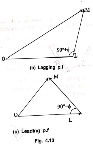
(i) Draw OL
representing If' to give
full‒load rated voltage, V. (or more exactly equal to V+ IRacosϕ)
Ref Fig. 4.13 (a).

(ii) Draw LM at an
angle (90° ± ϕ) representing If"
to give full‒load current on short circuit. (Ref Fig. 4.13 (b) and (c).
( +ve sign for lagging p.f and ‒ve sign for leading p.f)
(iii) Find field
current If, measuring OM,
which will give open circuit emf E0 which can be determined from
open circuit characteristic (OCC).
(iv) The percentage
regulation can be obtained from the following relation.
% regulation up = [ (E0‒V)
/ V ] × 100
Regulation given by
this method is much lower than that given by the synchronous impedance method.
But, it is nearer the correct value. This method is called then "Optimistic method.".
Basic Electronics and Electrical Engineering: Chapter 4: Synchronous Machines : Tag: Basic Engineering : Synchronous Machines - Determination of Voltage Regulation
Basic Electronics and Electrical Engineering: Chapter 4: Synchronous Machines
Under Subject

Basic Electronics and Electrical Engineering
EE25C04 1st Semester ECE Dept | 2025 Regulation | 2nd Semester 2025 Regulation
Related Subjects

English Essentials I
EN25C01 1st Semester | 2025 Regulation | 1st Semester 2025 Regulation

தமிழர் மரபு - Heritage of Tamils
UC25H01 1st Semester | 2025 Regulation | 1st Semester 2025 Regulation

Applied Calculus
MA25C01 Maths 1 M1 - 1st Semester | 2025 Regulation | 1st Semester 2025 Regulation

Applied Physics I
PH25C01 1st Semester | 2025 Regulation | 1st Semester 2025 Regulation

Applied Chemistry I
CY25C01 1st Semester | 2025 Regulation | 1st Semester 2025 Regulation

Makerspace
ME25C04 1st Semester | 2025 Regulation | 1st Semester 2025 Regulation

Computer Programming C
CS25C01 1st Semester | 2025 Regulation | 1st Semester 2025 Regulation

Computer Programming Python
CS25C02 1st Semester | 2025 Regulation | 1st Semester 2025 Regulation

Fundamentals of Electrical and Electronics Engineering
EE25C03 1st Semester | 2025 Regulation | 1st Semester 2025 Regulation

Introduction to Mechanical Engineering
ME25C03 1st Semester | 2025 Regulation | 1st Semester 2025 Regulation

Introduction to Civil Engineering
CE25C01 1st Semester Civil Department | 2025 Regulation | 1st Semester 2025 Regulation

Essentials of Computing
CS25C03 1st Semester - AID CSE IT Department | 2025 Regulation | 1st Semester 2025 Regulation

Applied Physics I Laboratory
PH25C01 1st Semester practical Laboratory Manual | 2025 Regulation | 1st Semester Laboratory 2025 Regulation

Applied Chemistry I Laboratory
CY25C01 1st Semester practical Laboratory Manual | 2025 Regulation | 1st Semester Laboratory 2025 Regulation

Computer Programming C Laboratory
CS25C01 1st Semester practical Laboratory Manual | 2025 Regulation | 1st Semester Laboratory 2025 Regulation

Computer Programming Python Laboratory
CS25C02 1st Semester practical Laboratory Manual | 2025 Regulation | 1st Semester Laboratory 2025 Regulation

Engineering Drawing
ME25C01 EEE Mech Dept | 2025 Regulation | 2nd Semester 2025 Regulation
Basic Electronics and Electrical Engineering
EE25C04 1st Semester ECE Dept | 2025 Regulation | 2nd Semester 2025 Regulation