Computer Organization and Architecture: Chapter 2: Arithmetic for Computers
Binary Multiplication
Arithmetic for Computers
Questions: 1. Explain an algorithm to multiply two positive numbers. Also discuss the realization of a multiplier to implement the same. 2. Explain the operation of sequential circuit binary multiplier with - Multiplicand 1101 , Multiplier 1011. 3. Draw flowchart for hardware multiplication algorithm and explain it. 4. Explain Booth's multiplication algorithm for multiplying binary integers in signed 2's complement representation. 5. Explain Booth's algorithm with flowchart. 6. Assume A = (+8) and B = (+5). Multiply these two numbers using Booth algorithm. Show the step‒by‒step multiplication process.
Binary Multiplication
1. Shift‒Add Method
•
The multiplication is a complex operation than addition and subtraction. It can
be performed in hardware or software.
•
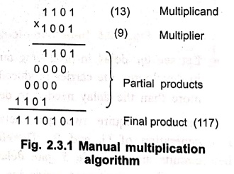
Fig. 2.3.1 shows the usual algorithm for multiplying positive numbers by hand.
•
Looking at this algorithms we can note following points:
■
Multiplication process involves generation of partial products, one for each
digit in the multiplier. These partial products are then summed to produce the final
product.
■
In the binary system the partial products are easily defined. When the
multiplier bit is 0, the partial product is 0, and when the multiplier is 1,
the partial product is the multiplicand.
■
The final product is produced by summing the partial products. Before summing
operation each successive partial product is shifted one position to the left
relative to the preceding partial product, as shown in Fig. 2.3.1.
■
The product of two n‒digit numbers can be accommodated in 2n digits, so the
product of the two 4‒bit numbers in fits into 8‒bits.
•
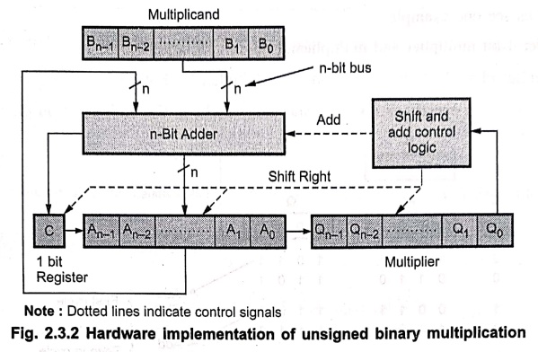
Fig. 2.3.2 shows the implementation of manual multiplication approach. It
consists of n‒bit binary adder, shift and add control logic and four registers,
A, B, C and Q.
•
As shown in Fig. 2.3.2 multiplier and multiplicand are loaded into register Q
and register B, respectively, and C are initially set to 0.
Note:
Dotted lines indicate control signals
Multiplication operation steps
1.
Bit 0 of multiplier operand (Q0 of Q register) is checked.
2.
If bit 0 (Q0) is one then multiplicand and partial product are added
and all bits of C, A and Q registers are shifted to the right one bit, so that
the C bit goes into An‒1, A0 goes into Qn‒1,
and Q0 is lost. If bit 0 (Q0) is 0, then no addition is performed,
only shift operation is carried out.
3.
Steps 1 and 2 are repeated n times to get the desired result in the A and Q
registers.
•
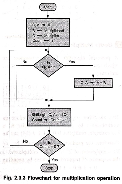
A flowchart for multiplication operation is shown in Fig. 2.3.3.
•
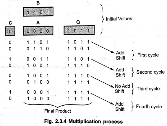
Let us see one example.
Consider
4‒bit multiplier and multiplicand:
Multiplicand
= 1 1 0 1 and Multiplier = 1 0 1 1
Fig.
2.3.4 shows operations involved and their results in the multiplication
process.
2. Booth Multiplier
•
A powerful algorithm for signed‒number multiplication is a Booth's algorithm,
which generates a 2n‒bit product and treats both positive and negative numbers
uniformly.
•
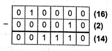
This algorithm suggest that we can reduce the number of operations required for
multiplication by representing multiplier as a difference between two numbers.
For example, multiplier 0 0 1 1 1 0 (14) can be represented as follows.
•
Therefore, the product can be computed by adding 24 times the
multiplicand to the 2's complement of 21 times the multiplicand. In
simple notations, we can describe the sequence of required operations by recoding the preceding multiplier as
0
+ 1 0 0 – 1 0
•
In general, for Booth's algorithm recoding scheme can be given as :
‒1 times the shifted
multiplicand is selected when moving from 0 to 1, +1 times the shifted
multiplicand is selected when moving from 1 to 0, and 0 times the shifted
multiplicand is selected for none of the above case, as multiplier is scanned
from right to left.
•
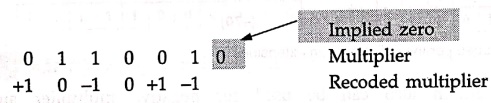
We have to assume an implied 0 to right of the multiplier LSB. This is
illustrated in the following examples.
Example: 1
Recode the multiplier 1 0 1 1 0 0
for Booth's multiplication.
Solution :

Example: 2
Recode the multiplier 0 1 1 0 0 1
for Booth's multiplication.
Solution :
•
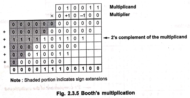
Fig. 2.3.5 shows the Booth's multiplication. As shown in the Fig. 2.3.5, whenever
multiplicand is multiplied by ‒1, its 2's complement is taken as a partial
result.
Multiplier:
0 0 1 1 0 0
Recoded
multiplier: 0 + 1 0 – 1 0 0
Multiplicand:
0 1 0 0 1 1
Note:
Shaded portion indicates sign extensions
•
The same algorithm can be used for negative multiplier. This is illustrated in
the following example.
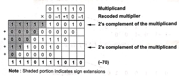
Example: 3
Multiply 0 1 1 1 0 (+14) and 1 1 0 1
1(‒5).
Solution :
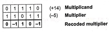
Multiplication:
Note:
Shaded portion indicates sign extensions
•
The same algorithm also can be used for negative multiplier and negative
multiplicand. This is illustrated in the following example.
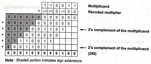
Example: 4
Explain the following pair of
signed 2's complement numbers.
Multiplicand: 1 1 0 0 1 1 (‒13)
Multiplier : 1 0 1 1 0 0 (‒20)
Solution :

Multiplication :
Note:
Shaded portion indicates sign extensions
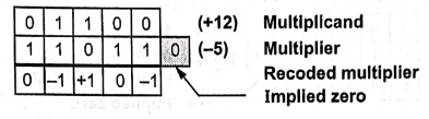
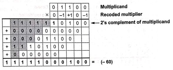
Example: 5
Using Booth's algorithm multiply the following:
Multiplicand+ 12
Multiplier = ‒5
Solution:
Multiplicand
= + 12 (0 1 1 0 0)
Multiplier
= ‒5 (1 1 0 1 1)
Multiplication :
Example: 6
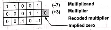
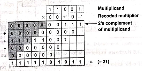
Multiply (‒7) and (+ 3) using
Booth's algorithm. Register size is 5 bits.
Solution:
Multiplicand
= ‒7 (1 1 0 0 1)
Multiplier
= + 3 (0 0 0 1 1)
Multiplication :
Example: 7
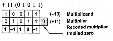
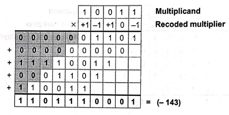
Using Booth's algorithm multiply
the following:
Multiplicand = ‒13
Multiplier = + 11
Solution:
Multiplicand
= ‒13 (1 0 0 1 1)
Multiplier
= + 11 (0 1 0 1 1)
Multiplication :
3. Hardware Implementation of Booth Multiplier
•
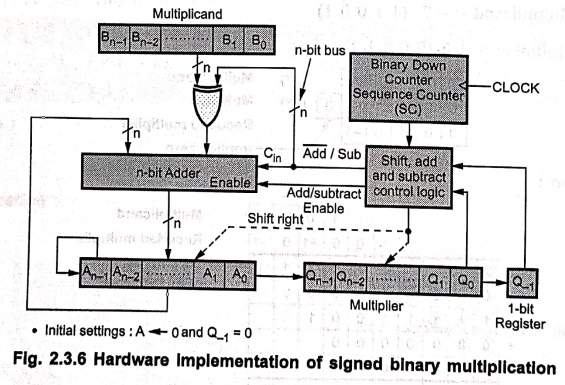
The Booth's algorithm can be implemented as shown in Fig. 2.3.6.
•
It consists of n‒bit adder, shift, add subtract control logic and four
registers, A, B, Q and Q‒1.
•
As shown in Fig. 2.3.6 multiplier and multiplicand are loaded into register Q
and register B, respectively, and register A and Q‒1 are initially
set to 0. The sequence counter, SC is set to a number n equal to the number of
bits in the multiplier.
•
The n‒bit adder performs addition of two inputs. One input is the A register
and other input is multiplicand. In case of addition,  line
is 0, therefore Cin=0 and multiplicand is directly applied as a
second input to the n‒bit adder.
line
is 0, therefore Cin=0 and multiplicand is directly applied as a
second input to the n‒bit adder.
•
In case of subtraction, line is 1, therefore Cin=
1 and multiplicand is complemented and then applied to the n‒bit adder. As a
result, the 2's complement of multiplicand is added in the A register.
•
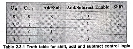
The shift, add and subtract control logic scans bits Q0 and Q‒1
one at a time and generates the control signals as shown in Table 2.3.1.
•
If the two bits are same (1 ‒ 1 or 0 ‒ 0), then all of the bits of the A, Q,
and Q‒1 registers are shifted to right 1‒bit without addition or
subtraction (Add/subtract RICEnable = 0).
•
If the two bits are differ, then the multiplicand (B‒register) is added to or
subtracted from the A register, depending on the status of bits.
•
If bits are Q0 = 0 and Q‒1 = 1 then multiplicand is added
and if bits are Q0= 1 and Q‒1 = 0 then multiplicand is
subtracted.
•
After addition or subtraction right shift occurs such that the leftmost bit of A
(An‒1) is not only shifted into An‒2, but also remains in
An‒1. This is required to preserve the sign of the number in A and
Q. It is known as an arithmetic shift, since
it preserves the sign bit.
•
After arithmetic shift, the sequence counter is decremented by 1 and if it is
not zero, computational loop is repeated. That is, in all computational loop is
repeated n‒times.
4. Flowchart of Booth's Multiplication Algorithm
The
sequence of events in Booth's algorithm can be explained with the help of
flowchart and algorithm shown in Fig. 2.3.7.
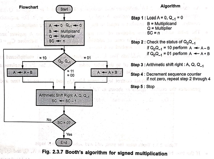
Algorithm
Step 1:
Load A = 0, Q‒1 = 0
B
= Multiplicand
Q
= Multiplier
SC
= n
Step 2:
Check the status of Q0Q‒1
If
Q0Q‒1 = 10 perform A←A‒B
If
Q0Q‒1=01 perform A← A+ B
Step 3:
Arithmetic shift right: A, Q, Q‒1
Step 4:
Decrement sequence counter
if
not zero, repeat step 2 through 4
Step 5: Stop
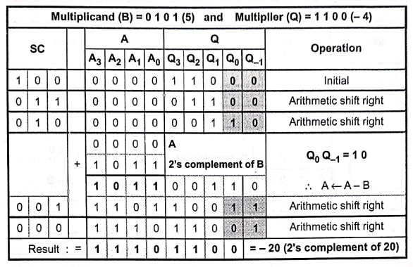
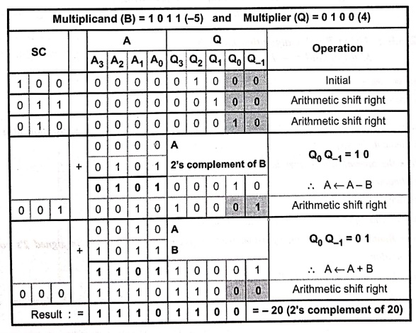
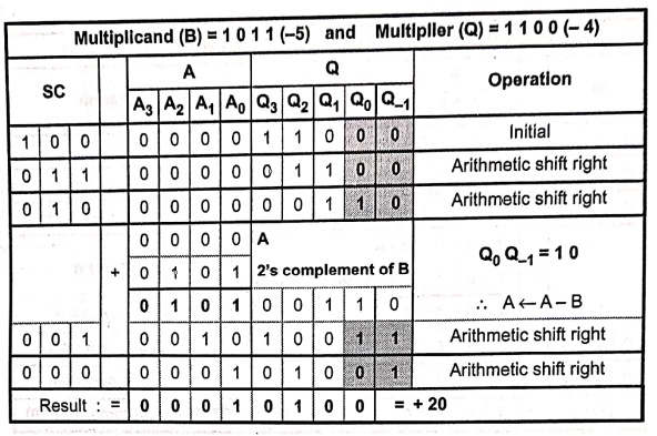
Let
us see the multiplication of 4‒bit numbers, 5 and 4 with all possible
combinations.
Case 1:
Both Positive (5 × 4)

Case 2:
Negative Multiplier ( 5 × ‒ 4)
Case 3:
Negative Multiplicand ( − 5 × 4)
Case 4:
Both Negative ( ‒5 × ‒4)
Examples for Practice
Example: 8
Using Booth's algorithm multiply
the following :
Multiplicand= + 13 Multiplier = ‒5
Example: 9
Using Booth's algorithm multiply
Multiplicand = ‒ 13 Multiplier = +
15.
Review Questions
1. Explain an
algorithm to multiply two positive numbers. Also discuss the realization of a
multiplier to implement the same.
2. Explain the
operation of sequential circuit binary multiplier with
Multiplicand 1101
Multiplier 1011.
3. Draw flowchart for
hardware multiplication algorithm and explain it.
4. Explain Booth's
multiplication algorithm for multiplying binary integers in signed 2's
complement representation.
5. Explain Booth's
algorithm with flowchart.
6. Assume A = (+8) and
B = (+5). Multiply these two numbers using Booth algorithm. Show the step‒by‒step
multiplication process.
Computer Organization and Architecture: Chapter 2: Arithmetic for Computers : Tag: Computer : Arithmetic for Computers - Binary Multiplication
Computer Organization and Architecture: Chapter 2: Arithmetic for Computers
Under Subject
Computer Organization and Architecture
CW25201 3rd Semester IT department. | 2025 Regulation | 3rd Semester 2025 Regulation
Related Subjects
Discrete Mathematics
MA25C14 3rd Semester CSE,IT,CY,AIDS departments. | 2025 Regulation | 3rd Semester 2025 Regulation
Data Structures
CS25C08 3rd Semester CSE,IT,CY,AIDS departments. | 2025 Regulation | 3rd Semester 2025 Regulation
Computer Organization and Architecture
CW25201 3rd Semester IT department. | 2025 Regulation | 3rd Semester 2025 Regulation
Object Oriented Programming
CS25C07 3rd Semester IT department. | 2025 Regulation | 3rd Semester 2025 Regulation
Web Technologies
IT25301 3rd Semester IT department. | 2025 Regulation | 3rd Semester 2025 Regulation
English Communication Skills Laboratory I
EN25C03 3rd Semester all department. | 2025 Regulation | 3rd Semester 2025 Regulation
Skill Development Course I
3rd Semester all department. | 2025 Regulation | 3rd Semester 2025 Regulation