Computer Organization and Architecture: Chapter 2: Arithmetic for Computers
Integer Arithmetic for Computers
1. 1's Complement Representation 2. 2's Complement Representation 3. Subtraction of Binary Numbers using 2's Complement Method 4. Adders 5. Ripple Carry Adder 6. 4‒bit Subtractor 7. Addition/ Subtraction Logic Unit 8. Overflow in Integer Arithmetic 9. Addition and Subtraction of Signed‒magnitude Data
Chapter 2:
Arithmetic
for Computers
Integer Arithmetic
•
We can relate addition and subtraction operations of numbers by the following
relationship :
(±
A) − (+B) = (± A) + (‒B) and (± A) ‒ (‒B) = (± A) + (+B)
•
Therefore, we can change subtraction operation to an addition operation by
changing the sign of the subtrahend.
1. 1's Complement Representation
The
1's complement of a binary number is the number that results when we change all
1's to zeros and the zeros to ones.
Example: 1
Find 1's complement of (11010100)2.
Solution :

2. 2's Complement Representation
The
2's complement is the binary number that results when we add 1 to the 1's
complement. It is given as
2's
complement = 1's complement + 1
The
2's complement form is used to represent negative numbers.
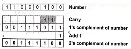
Example: 2
Find 2's complement of (11000100)2.
Solution :
3. Subtraction of Binary Numbers using 2's Complement Method
In
a 2's complement subtraction, negative number is represented in the 2's
complement form and actual addition is performed to get the desired result. For
example, operation A – B is performed using following steps:
1.
Take 2's complement of B.
2.
Result← A + 2's complement of B.
3.
If carry is generated then the result is positive and in the true form. In this
case, carry is ignored.
4.
If carry is not generated then the result is negative and in the 2's complement
form.
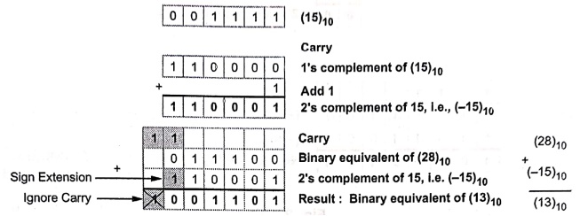
Example: 3
Perform (28)10 ‒ (15)10
using 6‒bit 2's complement representation.
Solution :
(28)10
= (011100)2
(15)10
= (001111)2
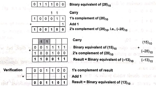
Example: 4
Perform (15)10 − (28)10
using 6‒bit 2's complement representation.
Solution:
(15)10
= (001111)2
(28)10 = (011100)2
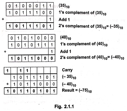
Example: 5
Perform (‒35) + (‒40) in binary
with negative numbers in 2's complement format.
Solution:
(35)10 = (0100011)2
(40)10 = (0101000)2
4. Adders
•
Digital computers perform various arithmetic operations.
•
The most basic operation, no doubt, is the addition of two binary digits. This
simple addition consists of four possible elementary operations, namely,
0
+ 0 = 0
0
+ 1 = 1
1+
0 = 1
1+
1 = 102
•
The first three operations produce a sum whose length is one digit, but when
the last operation is performed sum is two digits.
•
The higher significant bit of this result is called a carry, and lower significant bit is called sum.
The
logic circuit which performs this operation is called a half‒adder.
•
The circuit which performs addition of three bits (Two significant bits and a
previous carry) is a full‒adder.
1. Half Adders
•
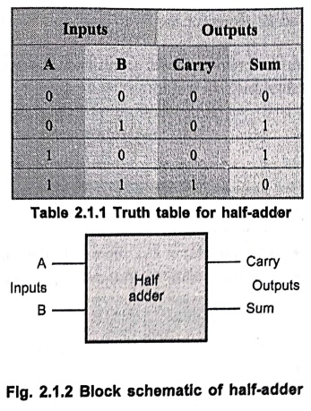
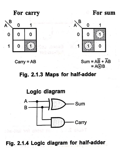
The half‒adder operation needs two binary inputs: Augend and addend bits; and
two binary outputs: Sum and carry.
•
The truth table shown in Table 2.1.1 gives the relation between input and
output variables for half‒adder operation.
Limitations of Half‒Adder
:
•
In multidigit addition we have to add two bits along with the carry of previous
digit addition.
•
Effectively such addition requires addition of three bits. This is not possible
with half‒adder. Hence half‒adders are not used in practice.
Example: 6
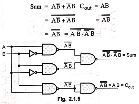
Draw half adder using NAND gates.
Solution:
For half adder :
2. Full Adders
•
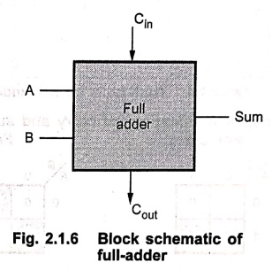
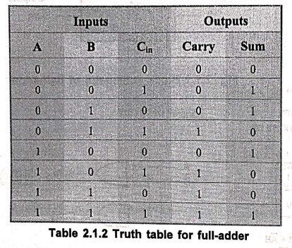
A full‒adder is a combinational circuit that forms the arithmetic sum of three
input bits.
•
It consists of three inputs and two outputs.
•
Two of the input variables, denoted by A and B, represent the two significant
bits to be added.
•
The third input Cin, represents the carry from the previous lower
significant position.
•
The truth table for full‒adder is shown in Table 2.1.2.
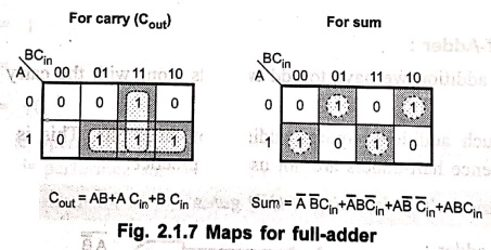
K‒map simplification for carry and
sum
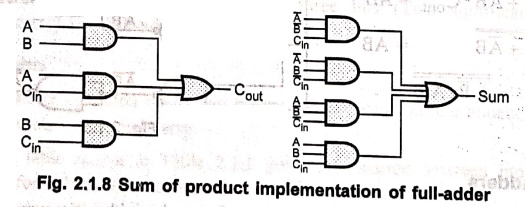
Logic dagram
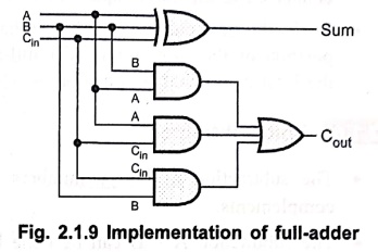
• The Boolean function for sum can be further simplified as follows:
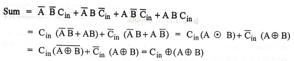
•
With this simplified Boolean function circuit for full‒adder can be implemented
as shown in Fig. 2.1.9.
•
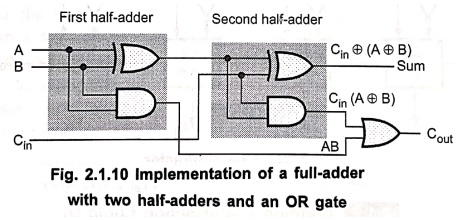
A full‒adder can also be implemented with two half‒adders and one OR gate, as
shown in Fig. 2.1.10.
•
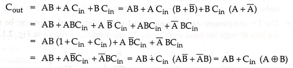
The sum output from the second half‒adder is the exclusive‒OR of Cin
and the output of the first half‒adder, giving
5. Ripple Carry Adder
•
A single full‒adder is capable of adding two one‒bit numbers and an input
carry. In order to add binary numbers with more than one bit, additional full‒adders
must be employed.
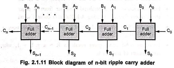
• A n‒bit, ripple carry adder can be constructed using number of full adder circuits connected in parallel.
•
Fig. 2.1.11 shows the block diagram of n‒bit ripple carry adder using n number
of full‒adder circuits connected in cascade, i.e. the carry output of each
adder is connected to the carry input of the next higher‒order adder.
•
It should be noted that either a half‒adder can be used for the least
significant position or the carry input of a full‒adder is made 0 because there
is no carry into the least significant bit position.
6. 4‒bit Subtractor
•
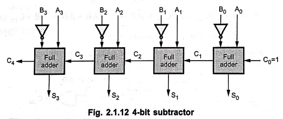
The subtraction of binary numbers can be done most conveniently by means of
complements.
•
The subtraction A ‒ B can be done by taking the 2's complement of B and adding
it to A. The 2's complement can be obtained by taking the 1's complement and
adding one to the least significant pair of bits.
•
The 1's complement can be implemented with inverters and a one can be added to
the sum through the input carry to get 2's complement, as shown in Fig. 2.1.12.
7. Addition/ Subtraction Logic Unit
•
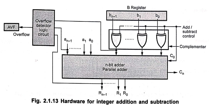
Fig. 2.1.13 shows hardware to implement integer addition and subtraction. It
consists of n‒bit adder, 2's complement circuit, overflow detector logic
circuit and AVF (overflow flag).
•
Number a and number b are the two inputs for n‒bit adder.
•
For subtraction, the subtrahend (number from B register) is converted into its
2's complement form by making Add/Subtract control signal to the logic one.
•
When Add/Subtract control signal is one, all bits of number b are complemented
and carry zero (Co) is set to one.
•
Therefore n‒bit adder gives result as R = a+ +
1, where +1 represents 2's complement of number b.
+
1, where +1 represents 2's complement of number b.
8. Overflow in Integer Arithmetic
•
When adding signed numbers, a carry bit beyond the end of the word does not
serve as the overflow indicator.
•
If we add the numbers + 7 and +3 in a 4‒bit adder, the output is 1010, which is
the code of ‒ 6, a wrong result. In this case, carry bit from the MSB position
is 0.
•
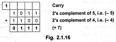
Similarly, if we add ‒ 5 and ‒ 6, we get output = + 5, another error. In this
case carry bit from the MSB position is 1.
•
One thing we can surely say that, the addition of numbers with different signs
cannot cause overflow, because the absolute value of the sum is always smaller
than the absolute value of one of the two operands.
•
From above discussion we can conclude following points:
1.
Overflow can occur only when adding two numbers that have the same sign.
2.
The carry bit from the MSB position is not a sufficient indicator of overflow
when adding signed numbers.
3.
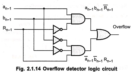
When both operands a and b have the same sign, an overflow occurs when the sign
of result does not agree with the signs of a and b. The logical expression to
path detect overflow can be given as
Overflow
= 
where
an‒1
= MSB of number a
bn‒1
= MSB of number b
Rn‒1
= MSB of the result
Example: 7
Give means to identify on whether
or not an overflow has occurred in 2's complement addition or subtraction
operations. Take one example for each possible situation and explain. Assume 4‒bit
registers.
Solution:
Case 1: Both numbers positive
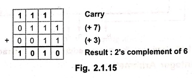
Result
is – 6 ; it is wrong due to overflow.
Case 2: Both numbers negative
Result
is +7 ; it is wrong due to overflow.
9. Addition and Subtraction of Signed‒magnitude Data
•
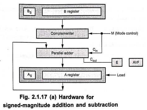
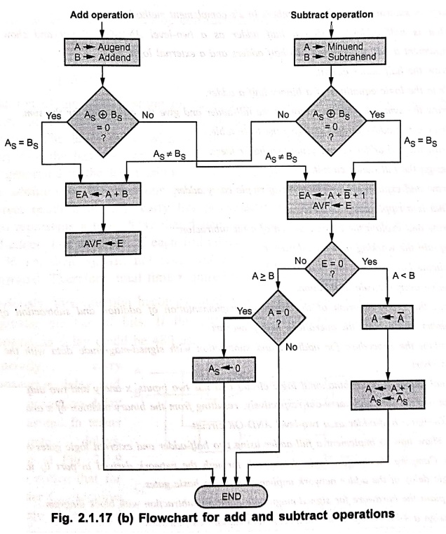
Fig. 2.1.17 shows the hardware and flowchart showing the procedure for addition
and subtraction with signed‒magnitude data.
•
Initially, signs of two numbers are compared by an exclusive‒OR gate. When
output of EX‒OR gate is 0, the signs are same if it is 1, the signs are
different.
•
For an add operation with equal signs or for a subtraction operation with
different signs magnitudes of numbers are added using micro‒operation EA ← A +
B, where EA is a register that combines E and A.
•
The carry in E after the addition constitutes an overflow if it is equal to 1.
It is then transfer into the add‒overflow flip‒flop AVF.
• The two magnitudes are subtracted if the signs are different for an add operation or same for a subtract operation. The magnitudes are subtracted by adding A to the 2's complement of B. Since magnitude of numbers are subtracted there is no overflow and AVF is clear to 0.
•
A = 1 in E indicates that A ≥ B and the number in A is the true result. If
result is zero, the sign As is made positive to avoid a negative
zero.
•
A = 0 in E indicates that A < B and the result is in A is not true. Here, it
is necessary to take 2's complement of the result. The 2's complement of result
can be performed using micro‒operation A← Ā +1.
•
The micro‒operation A← Ā +1 is carried out using operations :
A←Ā,
A←A +1, As ← Ā s
Review Questions
1. Write rule for
addition of two numbers.
2. Perform subtraction
of binary numbers in 2's complement method.
3. What is half adder?
Design a half adder as a two‒level AND‒OR circuit and show how to implement a
full adder using two half adders and a external logic gate.
4. Draw the half adder
circuit.
5. Write the logic
equations of a binary half a adder.
6. Draw the symbolic
representation of the full‒adder and give the expression for the sum.
7. Draw a full‒adder
circuit and give the truth table.
8. Draw the full adder
circuit using two half adders.
9. Design the full
adder circuit.
10. Draw and explain a
block diagram of ripple carry adder.
11. What is a ripple
carry adder?
12. Draw and explain
the block diagram of 4‒bit subtractor.
13. Explain the
working of 4‒bit subtractor.
14. Indicate how an
overflow is detected?
15. Define overflow
rule in addition.
16. Give the block
diagram of the hardware implementation of addition and subtraction of signed
number and explain the operations with flowchart.
17. Explain the
procedure for addition and subtraction with signed‒magnitude data with the help
of flowchart.
18. A half‒adder is a
combinational logic circuit that has two inputs, x and y and two outputs, s and
c, that are the sum and carry‒out respectively, resulting from the binary
addition of x and y.
i) Design a half‒adder
as a two‒level AND‒OR circuit.
ii) Show how to
implement a full‒adder using two half‒adder and external logic gates as
necessary.
iii) Compare the
longest logic delay path through the network derived in part ii) to that of the
logic delay of the adder network implemented using basic gates.
19. Explain the
hardware for signed‒magnitude addition subtraction with block diagram.
20. Design a 4‒bit
binary adder/subtractor and explain its functions.
21. Explain how
complement number system is useful in computer system. Discuss any one
complement number system with example.
22. Explain addition
and subtraction operations with signed 2's complement integer data. Support
your answer by taking appropriate example(s).
23. Design a digital
circuit for 4‒bit binary adder.
24. Draw and explain
flowchart for addition and subtraction operations with sign‒magnitude data.
Computer Organization and Architecture: Chapter 2: Arithmetic for Computers : Tag: Computer : - Integer Arithmetic for Computers
Computer Organization and Architecture: Chapter 2: Arithmetic for Computers
Under Subject
Computer Organization and Architecture
CW25201 3rd Semester IT department. | 2025 Regulation | 3rd Semester 2025 Regulation
Related Subjects
Discrete Mathematics
MA25C14 3rd Semester CSE,IT,CY,AIDS departments. | 2025 Regulation | 3rd Semester 2025 Regulation
Data Structures
CS25C08 3rd Semester CSE,IT,CY,AIDS departments. | 2025 Regulation | 3rd Semester 2025 Regulation
Computer Organization and Architecture
CW25201 3rd Semester IT department. | 2025 Regulation | 3rd Semester 2025 Regulation
Object Oriented Programming
CS25C07 3rd Semester IT department. | 2025 Regulation | 3rd Semester 2025 Regulation
Web Technologies
IT25301 3rd Semester IT department. | 2025 Regulation | 3rd Semester 2025 Regulation
English Communication Skills Laboratory I
EN25C03 3rd Semester all department. | 2025 Regulation | 3rd Semester 2025 Regulation
Skill Development Course I
3rd Semester all department. | 2025 Regulation | 3rd Semester 2025 Regulation