Basic Electronics and Electrical Engineering: Chapter 1: Basic Electronics
Capacitor
Fixed and Variable Capacitors | Symbol and Units, Working Principle, Color Coding, Symbol, Temperature Coefficient, Types, Example Problems
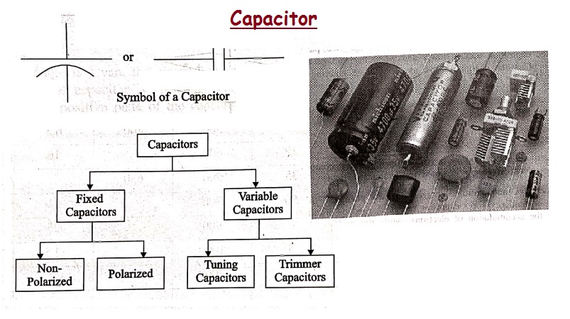
There are many types of capacitors depending upon their function, the dielectric material used, their shape etc. The main classification is done according to fixed and variable capacitors.
CAPACITOR
A Capacitor is a
passive component that has the ability to store the energy in the form of
potential difference between its plates. It resists a sudden change in voltage.
The charge is stored in the form of potential difference between two plates,
which form to be positive and negative depending upon the direction of charge
storage.
A non‒conducting region
is present between these two plates which is called as dielectric. This dielectric can be vacuum, air, mica, paper,
ceramic, aluminum etc. The name of the capacitor is given by the dielectric
used.
Symbol and Units
The standard units for
capacitance is Farads. Generally, the values of capacitors available will be in
the order of micro‒farads, pico‒farads and nano‒farads. The symbol of a capacitor
is as shown below.

The Capacitance of a
capacitor is proportional to the distance between the plates and is inversely
proportional to the area of the plates. Also, the higher the permittivity of a
material, the higher will be the capacitance. The permittivity of a medium describes how much electric flux is being
generated per unit charge in that medium. The following image shows some
practical capacitors.

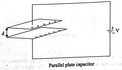
When two plates having
same area A, and equal width are placed parallel to each other with a
separation of distance d, and if some energy is applied to the plates, then the
capacitance of that parallel plate capacitor can be termed as
C = ε0εrA
/ d

Where
C = Capacitance of a
capacitor
ε0 =
permittivity of free space
εr =
permittivity of dielectric medium
d = distance between
the plates
A = area of the two
conducting plates
With some voltage
applied, the charge deposits on the two parallel plates of the capacitor. This
charge deposition occurs slowly and when the voltage across the capacitor
equals the voltage applied, the charging stops, as the voltage entering equals
the voltage leaving.
The rate of charging
depends upon the value of capacitance. The greater the value of capacitance,
the slower the rate of change of voltage in the plates.
Working of a Capacitor
A Capacitor can be
understood as a two‒terminal passive component which stores electrical energy.
This electrical energy is stored in electrostatic field.
Initially, the negative
and positive charges on two plates of the capacitor are in equilibrium. There
is no tendency for a capacitor to get charged or discharged. The negative
charge is formed by the accumulation of electrons, while the positive charge is
formed by the depletion of electrons. As this happens without any external
charge given, this state is electrostatic
condition. The figure below shows the capacitor with static charges.

The accumulation and
depletion of electrons according to the varying positive and negative cycles of
the AC supply, can be understood as "current flow". This is called as
Displacement Current. The direction
of this current flow keeps on changing as this is AC.
Charging of a Capacitor
When an external
voltage is given, the electric charge gets converted into electrostatic charge.
This happens while the capacitor is charging. The positive potential of the
supply, attracts the electrons from the positive plate of the capacitor, making
it more positive. While the negative potential of the supply, forces the electrons
to the negative plate of the capacitor, making it more negative. The figure 1.17
below explains this.
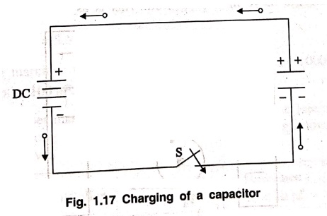
Figure showing the
electrons from positive plate to deposit on negative plate of a capacitor.
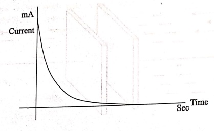
During this process of
charging, the electrons move through the DC supply but not through the dielectric which is an insulator. This displacement is large,
when the capacitor starts to charge but reduces as it charges. The capacitor
stops charging when the voltage across capacitor equals the supply voltage.
Let us see what happens
to the dielectric when the capacitor begins to charge.
Dielectric behavioral
As the charges deposit
on the plates of the capacitor, an electrostatic field is formed. The strength
of this electrostatic field depends upon the magnitude of charge on the plate
and the permittivity of the dielectric material. Permittivity is the measure of dielectric whether how far it allows
the electrostatic lines to pass through it.
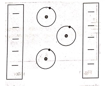
The dielectric is
actually an insulator. It has electrons in the outer most orbit of the atoms.
Let us observe how they get affected. When there is no charge the plates, the
electrons in the dielectric move in circular orbit. This is as shown in the
figure below.
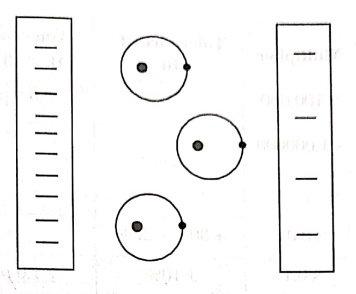
When charge deposition
takes place, the electrons tend to move towards the positive charged plate, but
still they keep on revolving as shown in the figure.
If the charge increases
further, the orbits expand more. But if it still increases, the dielectric breaks down shorting the capacitor.
Now, the capacitor being fully charged, it's ready to get discharged. It is
enough if we provide a path for them to travel from negative to positive plate.
The electrons flow without any external supply as there are too many number of
electrons on one side and barely any electrons on the other. This imbalance is
adjusted by the discharge of the
capacitor.
Also, when a discharge
path is found, the atoms in the dielectric material tend to get to their normal
circular orbit and hence forces the
electrons to get discharged. This kind of discharge enables capacitors to
deliver high currents in a short period of time, just as in a camera flash.
Color Coding
To know the value of a
capacitor, it is usually labelled as below
n35 = 0.35 nF or 3n5 =
3.5 nF or 35n=35 nFand so on.
Sometimes the markings
will be like 100 K which means, k =
1000 pF. Then the value will be 100 × 1000 pF = 100 nF.
Though these number
markings are being used now‒a‒days, an International color coding scheme was
developed long ago, to understand the values of capacitors. The color coding
indications are just as given below.

These indications were
used to identify the value of capacitors.
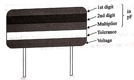
In these five band
capacitors, the first two bands represent digits, third one indicates
multiplier, fourth for tolerance and the fifth represents voltage. Let us look
at an example to understand the color coding process.
Example
1: Determine the value of a capacitor with a color code yellow, violet, orange,
sword white and red.
Solution
The value of yellow is
4, violet is 7, orange is 3 which represents multiplier. White is 10 which is
the tolerance value. Red represents the voltage. But to know the voltage
rating, we have got another table, from which the particular band to which this
capacitor belongs, has to be known.
Hence the value of the
capacitor is 47 nF, 10% 250 V voltage for V band voltage for V band.
The following table
shows how voltage is determined depending upon the bands the capacitors belong
to.

With the help of this
table, the voltage rating for each band of capacitors is known according to the
color given. The type of voltage ratings also indicates the type of capacitors.
For example, TYPE J ones are Dipped Tantalum Capacitors, TYPE K ones are Mica
Capacitors, TYPE L ones are Polystyrene Capacitors, TYPE M ones are
Electrolytic Band 4 Capacitors and TYPE N ones are Electrolytic Band 3
Capacitors. These days, the color coding has been replaced by simple printing
of value of the capacitors as mentioned previously.
Capacitive Reactance
This is an important
term. Capacitive Reactance is the opposition offered by a capacitor to the
alternating current flow, or simply AC current. A capacitor resists the change
in the flow of current and hence it shows some opposition which can be termed
as reactance, as the frequency of
the input current should also be considered along with the resistance it offers.
Symbol: Xc
In a purely capacitive
circuit, the current Ic leads the applied voltage by 90°.
Temperature Coefficient of Capacitors
The maximum change in Capacitance of a capacitor, over a
specified temperature range, can be known by the temperature coefficient of a
capacitor. It states that when the temperature exceeds a certain point, the
change in capacitance of a capacitor that might occur is understood as the temperature coefficient of capacitors.
All the capacitors are
usually manufactured considering a reference temperature of 25°C. Hence the
temperature coefficient of capacitors is considered for the values of
temperatures that are above and below this value.
Types of Capacitors
There are many types of
capacitors depending upon their function, the dielectric material used, their
shape etc. The main classification is done according to fixed and variable
capacitors. The classification is as shown below.

• Fixed Capacitors: Non‒ Polarized, Polarized
• Variable Capacitors: Tuning Capacitors, Trimmer Capacitors
The main classification
is just like the above one. The fixed capacitors are the ones whose value is
fixed at the time of manufacturing itself and the variable ones provide us with
an option to vary the value of capacitance.
1. Fixed Capacitor
The Capacitors whose
value is fixed while manufacturing and cannot be altered later are called as Fixed Capacitors. The main
classification of fixed capacitors is done as polarized and non‒polarized. Let
us have a look at Non‒polarized capacitors.
Non‒Polarized
Capacitors
These are the
capacitors that have no specific
polarities, which means that they can be connected in a circuit, either way
without bothering about the placement of right lead and left lead. These
capacitors are also called as Non‒Electrolytic
Capacitors.
The main classification
of Non‒Polarized capacitors is done as shown below.

1.1 Ceramic Capacitors
The common capacitors
used among fixed type are Ceramic Capacitors. The Ceramic capacitors are fixed
capacitors that have ceramic material
as a dielectric.
These ceramic
capacitors are further classified as class1 and class2 depending upon their
applications. For instance, Class1
has high stability and works best for resonant circuit applications, while class2 has high efficiency and gives
its best for coupling applications.
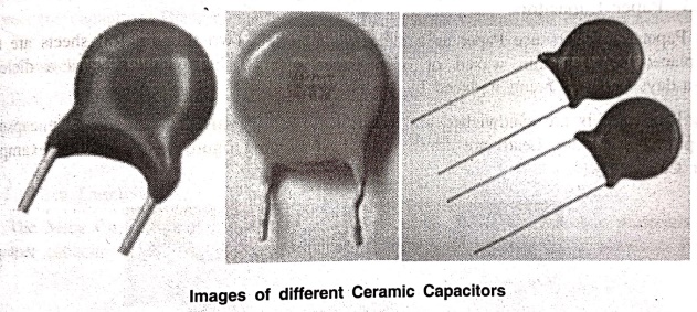
A hollow tubular or
plate like ceramic material such as titanium
dioxide and barium titanate is
coated with a deposition of silver compound on both walls, so that both sides
act as two capacitor plates and ceramic acts as a dielectric. Leads are drawn
from these two surfaces and this whole assembly is encapsulated in a moisture‒proof
coating.
The most often used modern ceramic capacitors are Multi‒Layer Chip Capacitors (MLCC). These capacitors are made in surface mounted technology and are mostly used due to their small size. These are available in the order of 1cF to 100%F.
1.2 Film Capacitors
The Film Capacitors are
the ones which have a film substance as a dielectric material. Depending upon
the type of film used, these are classified as Paper and Metal film capacitors.
These film capacitors
are both paper dielectric capacitors whereas a paper capacitor uses a waxed paper while a metallic film
capacitor uses a metallized paper.
The arrangement is almost same as shown below.
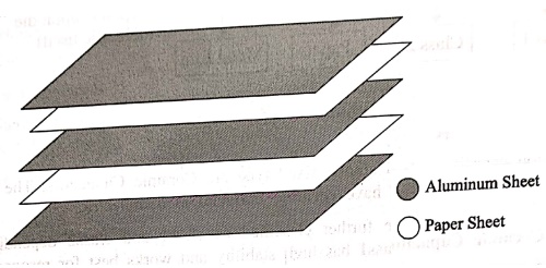
1.3 Paper Capacitors
Paper capacitors use
Paper as a dielectric material. Two thin tin foil sheets are taken and placed
between thin waxed or oiled paper sheets. This paper acts as a dielectric. Now‒a‒days
paper is being replaced by plastic.
These sheets are
sandwiched and are rolled into a cylindrical shape and encapsulated in a
plastic enclosure. Leads are drawn out. The following figure 1.18 shows an
example of Paper Capacitors.
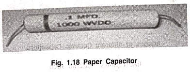
Paper capacitors are
available in the order of 0.001%F to 2% F and the voltage rating can be as high
as 2000volts. These capacitors are useful in high voltage and current
applications.
1.4 Metal Film Capacitors
Metal Film capacitors
are another type of film capacitors. These are also called as Metal Foil
Capacitors or Metallized Paper Capacitors as the dielectric used here is a
paper coated with metallic film.
Unlike in paper
capacitors, a film of Aluminum or Zinc is coated on a paper to form a
dielectric in this metallic film capacitors. Instead of Aluminum sheets placing
between papers, the paper itself is directly coated here. This reduces the size
of the capacitor.
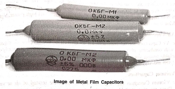
The Aluminum coating is
preferred over zinc coating so as to avoid
destruction of capacitor due to chemical reduction. The Aluminum coated sheets
are rolled in the form of a cylinder and leads are taken. This whole thing is
encapsulated with wax or plastic resin to protect the capacitor. These
capacitors are useful in high voltage
and current applications.
Other
Capacitors
These are the
miscellaneous capacitors that are named after the dielectric materials used.
This group includes Mica Capacitors, Air Capacitors, Vacuum Capacitors and
Glass Capacitors
1.5 Mica Capacitors
The Mica Capacitors are
made by using thin Mica sheets as dielectric materials. Just like paper
capacitors, thin metal sheets are sandwiched with mica sheets in between.
Finally the layers of metal sheets are connected at both ends and two leads are
formed.
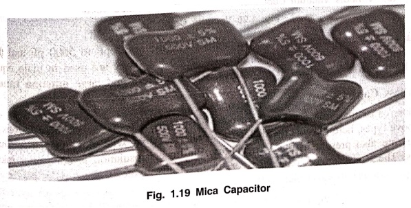
Then the whole assembly
is enclosed in plastic Bakelite capsule. The following figure 1.19 shows how a
Mica capacitor looks like.
Mica Capacitors are
available in the range of 50pF to 500pF. The Mica capacitors have high working
voltage up to 500volts. These are most commonly used capacitors for electronic
circuits such as ripple filters, Resonant circuits, Coupling circuits and high
power, high current RF broadcast transmitters.
1.6 Air Capacitors
The Air Capacitors are
the ones with air as dielectric. The
simplest air capacitors are the ones with conducting plates having air in
between. This construction is exactly the same as the variable tuning capacitor discussed above. These capacitors can be
fixed and variable also but fixed are very rarely used as there are others with
superior characteristics.
1.7 Vacuum Capacitors
The Vacuum Capacitors
uses high vacuum as dielectric
instead of air or some other material. These are also available. in fixed and
variable modes. The construction of these
capacitors is similar
to vacuum tubes. They are mostly seen in the form of a glass cylinder which
contain inter‒meshed concentric cylinders.
The following figure
1.20 shows a variable vacuum and fixed vacuum capacitor.

Variable vacuum
capacitors are available at a range of 12 pF to 5000 pF and they are used for
high voltage applications such as 5 kV to 60 kV. They are used in main equipment
such as high power broadcast
transmitters, RF amplifiers and large antenna
tuners.
1.8 Glass Capacitors
Glass capacitors are
very exclusive ones with many advantages and applications. As all of the above
types, here glass is the dielectric
substance. Along with glass dielectric, Aluminum electrodes are also present in
these capacitors. Plastic encapsulation is done after taking out the leads. The
leads can be axial leads or tubular leads,

There are many
advantages of a glass capacitor such as ‒
• The temperature
coefficient is low.
• These are Noise‒free
capacitors.
• They produce high
quality output with low loss.
• They have the
capability of handling high operating temperatures.
• These capacitors can
handle large RF currents.
There are many
applications for these glass capacitors such as
• Used in circuits that
need to be at high temperature zones.
• Used in circuits that
need high Q.
• Used in high power
handling circuits.
• Used for circuits
that need high tolerances.
2. Variable Capacitors
Let us know something
about the variable capacitors whose value alters when you vary, either electrically or mechanically. Variable capacitors in general consists of interwoven
sets of metallic plates in which one is fixed and the other is variable. These
capacitors provide the capacitance values so as to vary between 10 to 500 pF.

The ganged capacitor
shown here is a combination of two capacitors connected together. A single
shaft is used to rotate the variable ends of these capacitors which are
combined as one. The dotted line indicates that they are connected internally.
There are many uses of
these variable resistors such as for tuning in LC circuits of radio receivers,
for impedance matching in antennas etc. The main types of variable capacitors
are Tuning capacitors and Trimmer capacitors.
2.1 Tuning Capacitors
Tuning capacitors are
popular type of variable capacitors. They contain a stator, a rotor, a frame to
support the stator and a mica capacitor. The constructional details of a tuning
capacitor are shown in the following figure 1.22.
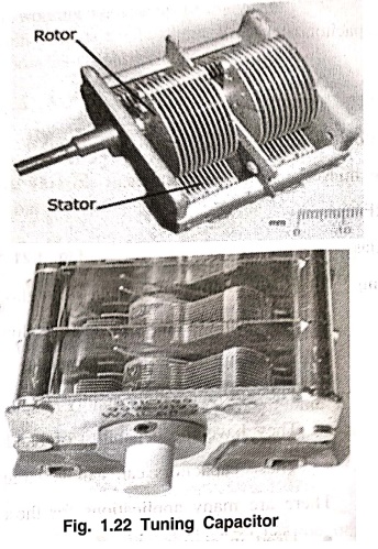
The stator is a
stationary part and rotor rotates by the movement of a movable shaft. The rotor
plates when moved into the slots of stator, they, come close to form plates of
a capacitor. When the rotor plates sit completely in the slots of the stator
then the capacitance value is maximum and when they don't, the capacitance
value is minimum.
The above figure 1.22
shows a ganged tuning capacitor
having two tuning capacitors connected in a gang. This is how a tuning
capacitor works. These capacitors generally have capacitance values from few
Pico Farads to few tens of Pico Farads. These are mostly used in LC circuits in
radio receivers. These are also called as Tuning
Condensers.
2.2 Trimmer Capacitors
Trimmer capacitors are
varied using a screwdriver. Trimmer capacitors are usually fixed in such a
place where there is no need to change the value of capacitance, once fixed.
There are three leads
of a trimmer capacitor, one connected to stationary plate, one to rotary and
the other one is common. The movable disc is a semi‒circular shaped one. A
trimmer capacitor would look like the ones in the following figure 1.23.
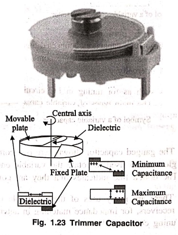
There are two parallel
conducting plates present with a dielectric in the middle. Depending upon this
dielectric used, there are air trimmer capacitors and ceramic trimmer
capacitors. The constructional details of a trimmer capacitor are as shown fig.
1.23.
One of the two plates
is movable, while the other is fixed. The dielectric material is fixed. When
the movable plate is moved, opposite to the area between movable and fixed
electrode, then the capacitance can be changed. The capacitance will be higher
if the opposite area gets bigger, as both the electrodes act as two plates of a
capacitor.
The Trimmer Capacitors
are easily fixed on a PCB (Printed Circuit Board) and they are mostly used for
calibration of equipment.
Basic Electronics and Electrical Engineering: Chapter 1: Basic Electronics : Tag: Basic Engineering : Fixed and Variable Capacitors | Symbol and Units, Working Principle, Color Coding, Symbol, Temperature Coefficient, Types, Example Problems - Capacitor
Basic Electronics and Electrical Engineering: Chapter 1: Basic Electronics
Under Subject

Basic Electronics and Electrical Engineering
EE25C04 1st Semester ECE Dept | 2025 Regulation | 2nd Semester 2025 Regulation
Related Subjects

English Essentials I
EN25C01 1st Semester | 2025 Regulation | 1st Semester 2025 Regulation

தமிழர் மரபு - Heritage of Tamils
UC25H01 1st Semester | 2025 Regulation | 1st Semester 2025 Regulation

Applied Calculus
MA25C01 Maths 1 M1 - 1st Semester | 2025 Regulation | 1st Semester 2025 Regulation

Applied Physics I
PH25C01 1st Semester | 2025 Regulation | 1st Semester 2025 Regulation

Applied Chemistry I
CY25C01 1st Semester | 2025 Regulation | 1st Semester 2025 Regulation

Makerspace
ME25C04 1st Semester | 2025 Regulation | 1st Semester 2025 Regulation

Computer Programming C
CS25C01 1st Semester | 2025 Regulation | 1st Semester 2025 Regulation

Computer Programming Python
CS25C02 1st Semester | 2025 Regulation | 1st Semester 2025 Regulation

Fundamentals of Electrical and Electronics Engineering
EE25C03 1st Semester | 2025 Regulation | 1st Semester 2025 Regulation

Introduction to Mechanical Engineering
ME25C03 1st Semester | 2025 Regulation | 1st Semester 2025 Regulation

Introduction to Civil Engineering
CE25C01 1st Semester Civil Department | 2025 Regulation | 1st Semester 2025 Regulation

Essentials of Computing
CS25C03 1st Semester - AID CSE IT Department | 2025 Regulation | 1st Semester 2025 Regulation

Applied Physics I Laboratory
PH25C01 1st Semester practical Laboratory Manual | 2025 Regulation | 1st Semester Laboratory 2025 Regulation

Applied Chemistry I Laboratory
CY25C01 1st Semester practical Laboratory Manual | 2025 Regulation | 1st Semester Laboratory 2025 Regulation

Computer Programming C Laboratory
CS25C01 1st Semester practical Laboratory Manual | 2025 Regulation | 1st Semester Laboratory 2025 Regulation

Computer Programming Python Laboratory
CS25C02 1st Semester practical Laboratory Manual | 2025 Regulation | 1st Semester Laboratory 2025 Regulation

Engineering Drawing
ME25C01 EEE Mech Dept | 2025 Regulation | 2nd Semester 2025 Regulation
Basic Electronics and Electrical Engineering
EE25C04 1st Semester ECE Dept | 2025 Regulation | 2nd Semester 2025 Regulation