Basic Electronics and Electrical Engineering: Chapter 1: Basic Electronics
Resistors
Fixed and Variable Resistors | Types, Specification, Symbol, Units, Color Coding, Example Problems, Construction, Applications
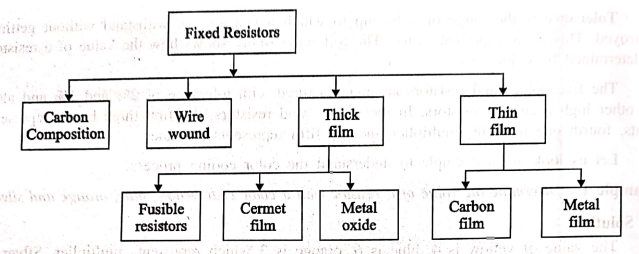
A resistor is an electrical/electronic passive component used to limit the flow of current. The figure represents the various types of resistors.
RESISTORS
A resistor is an
electrical/electronic passive component used to limit the flow of current. The
figure represents the various types of resistors.
Specification of Resistors:
The specification of
resistors are :
1. Resistance value
2. Tolerance
3. Power rating
4. Thermal stability
1. Resistance value (Ohmic value)
The magnitude of the
resistor has been expressed in terms of its resistance value. The resistance
value decides the quantity of current flow to be opposed. Thus the resistance
value is expressed in ohms. (Ω) or kilo‒ohms (KΩ) or mega‒ohms (MΩ). The
resistance value is either printed on the surface of a resistor or by color
bands.
2. Tolerance
Tolerance represents
the maximum and minimum values of a resistance value. It is specified in terms
of percentage. It is been expressed as either +% on the surface of the resistor
or with the help of a fourth color band.
3. Power Rating (Wattage Rating)
Power rating specifies
the maximum power in watts that the resistor can handle without being destroyed
or damaged. It also represents the power dissipation in the resistor in terms
of I2R loss (or heat).
4. Thermal Stability
Thermal stability
indicates the stability in the resistance value to a maximum specified
temperature. or It is the ability of a resistor to maintain the same resistance
value with variation in temperature.
Types of Resistor and their Symbols:
Based on their
operation following are the types of resistor:
1. Fixed
resistor
(a) Wire
Wound Resistors
(i) Power
type wire wound resistor
(ii)
Precision type wire‒wound resistor
(b)
Carbon Composition Resistors
(c)
Cracked Carbon Resistors or Carbon Film Resistors
(d) Metal
Oxide Resistors
(e) Metal
Film Resistors
2.
Variable resistor
(a)
Continuously variable resistors
(i)
Potentiometers
(ii)
Rheostats
(b)
Adjustable or pre‒set resistors
(i)
Decade resistance boxes
(ii)
Thermistors
(iii)
Varistors.
3. Tapped
resistors
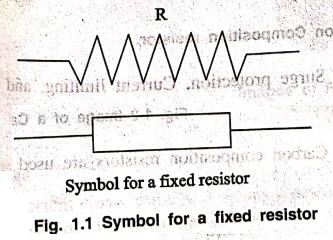
Symbol and Units
Symbol for a resistor
is as shown below.
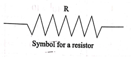
The units of resistance
is Ohms, which is indicated by Ω.
The formula for
resistance is
R = V/I
Where V is Voltage and
I is Current. It would really be difficult to manufacture the resistors with
each and every value. Hence, few values are chosen and the resistors of such
values are only manufactured. These are called as "Preferred Values". In practice, the resistors with near
values are chosen to match the required applications.

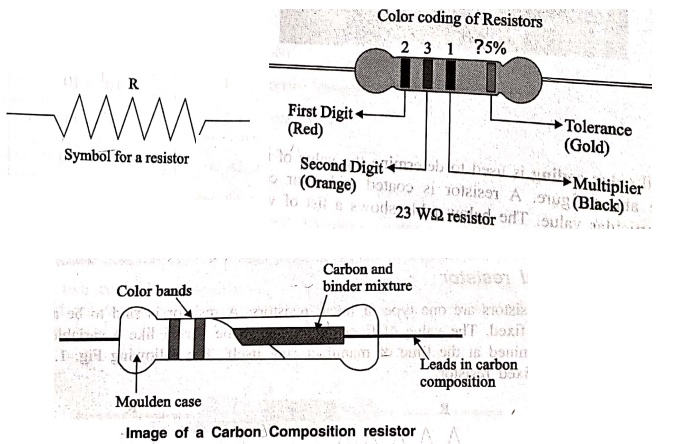
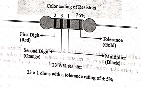
Color Coding
A process called color
coding is used to determine the value of resistance for a resistor, just as
shown in the above figure. A resistor is coated with four color bands where
each color determines a particular value. The below table shows a list of
values which each color
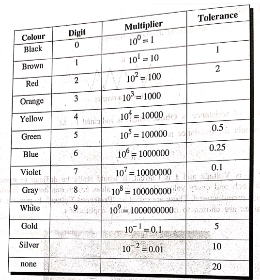
The first two colored
bands indicate the first and second digit of the value and the third color band
represents the multiplier number of zeroes added number of zeroes added. The
fourth color band indicates the tolerance value.
Tolerance
is the range of value up to which a resistor can withstand without getting destroyed.
This is an important factor. The following figure shows how the value of a
resistor is determined by color code.
The five color band
resistors are manufactured with tolerance of 2% and 1% and also for other high
accuracy resistors. In these five band resistors, the first three bands
represent digits, fourth one indicates multiplier and the fifth represents
tolerance.
Let us look at an
example to understand the color coding process.
Example
1: Determine the value of a resistor with a color code yellow, blue, orange and
silver.
Solution
The value of yellow is
4, blue is 6, orange is 3 which represents multiplier. Silver is 10 which is
the tolerance value.
Hence the value of the
resistor is 46 × 103 = 46 kΩ
The maximum resistance
value for this resistor is
46 ΚΩ or 46000 Ω + 10%
= 46000 + 4600 = 50600 Ω = 50.6 ΚΩ
The minimum resistance
value for this resistor is
46 ΚΩ or 46000 Ω ‒ 10%
= 46000 ‒ 4600 = 41400 Ω= 414 ΚΩ
After having gone
through different details regarding resistors, we have some terms to learn.
Also we have to deal with different behaviors of a resistor for few types of
connections.
1. Fixed resistor
Fixed resistors are one
type of linear resistors. A resistor is said to be a fixed resistor, if its
value is fixed. The value of fixed resistor can't be varied like a variable
resistor as its value is determined at the time of manufacturing itself. The
following Fig. 1.1 represent the symbol of a fixed resistor.
The fixed resistors are
classified into different types, depending upon their manufacturing processes
and the materials used in their manufacturing. The classification is as
follows,
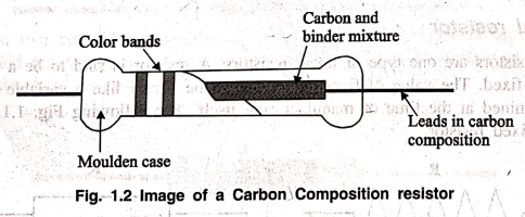
1.1 Carbon Composition
The Carbon composition
resistors are a blend of carbon particles, graphite and ceramic dust mixed with
a binder substance like clay. This mixture is treated with high pressure and
temperature. After the whole thing is molded in a case, the leads are fixed.
• Thermal, mass of the
carbon composition resistor is higher so as to withstand high energy pulses.
• These resistors have
low stability and high noise which is a disadvantage.
The following figure
1.2 shows an image of carbon composition resistor.
Carbon composition
resistors are used in Surge protection, Current limiting, and High voltage
power supplies.
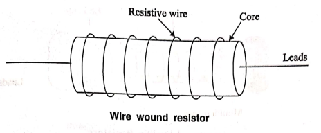
1.2 Wire wound
A Wire wound resistor
is formed by wounding a wire made up of a resistive material around a core. The
metallic core acts as a non‒conductive material while the resistive, wire
conducts, but with some resistance. The image of a wire wound resistor is as
shown below.
Usually a nichrome wire
or a manganin wire is used to wind the core because they offer high resistance.
Whereas plastic, ceramic or glass is used for core.
• Wire wound resistors
are very accurate.
• They work excellently
for low resistance values and high power ratings.
These are the oldest
type of fixed resistors, but are being used even now.
1.3 Thick Film
The film resistors have
a resistive layer on a ceramic base, whose thickness defines the type they
belong to. The thickness of resistive layer on thick film resistors is much
higher than thin film resistors. Thick film resistors are produced by firing a
special paste, which is a mixture of glass and metal oxides, onto the
substrate.
There are three main
types in thick film resistors like Fusible resistors, Cermet film resistors,
and Metal oxide film resistors.
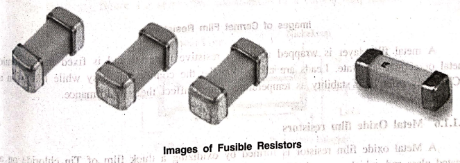
1.4 Fusible Resistors
The Fusible resistors
are similar to wire wound resistors. But these resistors along with providing
resistance, act as a fuse. The image of a fusible resistor is as shown below.
In this resistor, the
current flows through a spring loaded connection, which is placed closely to
the body of the resistor. The blob that is attached to the spring resistor takes
the heat generated by the resistor due to the current flow. If this heat is
increased, the attachment to the blob gets melted up and opens the the
connection.
Hence we can say that,
these resistors limit the current, but if the circuit power rating exceeds a
specified value, these resistors act as a fuse to open or break the circuit.
The value of these resistors is usually of less than 10 Ohms.

These resistors are
generally used in TV sets, amplifiers and other expensive electronic circuits.
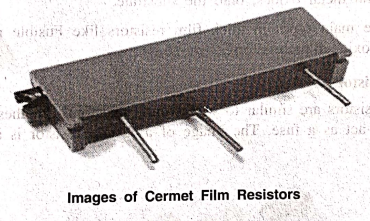
1.5 Cermet Film Resistors
The Cermet film
resistors are the film resistors made up of a special material called Cermet.
Cermet is a composite alloy made by combining Ceramic and Metal. This re
resistance combination provides the advantages in both of these materials like
high temperature resistance and wear resistance of ceramic along with
flexibility and electrical conductivity of a metal.
A metal film layer is
wrapped around a resistive material and is fixed in a ceramic metal or cermet
substrate. Leads are taken to make the connections easy while fixing on a PCB.
They offer high stability as temperature cannot affect their performance.
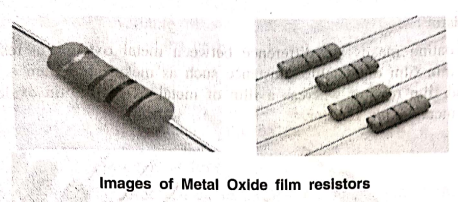
1.6 Metal Oxide film resistors
A Metal oxide film
resistor is formed by oxidizing a thick film of Tin chloride on a heated glass
rod, which is a substrate. They have high temperature have high temperature
stability and can be used at high voltages. These resistors have low operating
noise.
Metal oxide film
resistors differ with metal film ones only regarding the type of film coated.
Metal oxide is a metallic compound like tin with oxygen to form tin oxide,
which is coated as a film on the resistor. The resistivity of this resistor
depends upon the amount of antimony oxide added to the tin oxide.
1.7 Thin Film
Thin film resistors
have a resistive layer of width 0.1 micrometer or smaller on the ceramic base.
Thin film resistors have a metallic film that is vacuum deposited on an
insulating substrate.
Thin film resistors are
more accurate and have better temperature coefficient and is more stable. The
thin film resistors are further divided into two types such as ‒
• Carbon film resistors
• Metal film resistors
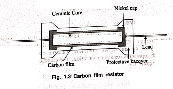
Carbon film resistors
A Carbon film resistor
is made by depositing a carbon film layer on a ceramic substrate. The carbon
film acts as the resistive material to the current and the ceramic substance
acts as an insulating substance. Metallic caps are fixed at both the ends and
copper leads are drawn out.
The following figure
1.3 shows the construction of a carbon film resistor.
The main advantages of
these resistors are their high stability, wide operating range, low noise, and
low cost. The carbon film resistors are the most preferred ones over carbon
composition resistors due to their low noise.
Metal Film Resistors
The film coating makes
the difference between metal oxide film resistors and metal film resistors. A
thin film of metallic substance such as nickel chromium is used to coat the
resistor in a metal film resistor whereas a film of metal oxide like tin oxide
is used to coat the resistor in a metal oxide resistor.
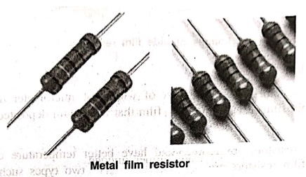
Metal film resistors have
low temperature coefficient of resistance, which means the resistance is less
affected by the temperature.
Wattage
While using a resistor,
if the flow of current increases, the resistor dissipates some heat. If this
value crosses a certain critical value, the resistor may get damaged. The
wattage rating of a resistor is printed on some higher value resistors in order
to avoid such situation.
Wattage is the amount
of electric power expressed in watts. Electric power is the rate of transfer of
electrical energy.
Power P=VI=I2R
2. Variable Resistors
The variable resistor
is a passive, three terminal device that can adjust its resistance via third
terminal located between two terminals so that the obstruction to the flow of
current goes up and down. Therefore, variable resistor circuit symbol has an
arrow which represents resistance variation. The electrical symbol of variable
resistor shown in Figure 1.4.

The resistance of a
variable resistor can be changed between zero to a certain maximum value with
its third terminal. When the circuit diagram of the variable resistor in Figure
1.4 is carefully examined, you can see constant resistance exist between the
terminals 1 and 3. Terminal 2 (in the middle) is the only terminal which has
the ability to move. Therefore, in order to change resistance you must use
anyone of the side terminals with the moving terminal.
Operation Principles of Variable Resistors
Variable resistors are
widely used in electric circuits to adjust the value of current or voltage,
since the resistance of variable resistors can be set to a certain value.
Variable resistors allow you to adjust the value of voltage by changing the
resistance and keeping current constant. To adjust the input voltage, a voltage
source is connected to the terminals 1 and 3 as shown in Figure 1.5. The output
voltage between terminals 1 and 2 can be calculated by the voltage division
formula

Voltage Division Formula
Construction of a Variable Resistór
Although there are different
types of variable resistors, their working principle is the same. When the
inside of a variable resistor is examined such as Fig. 7,6, there is a fixed
resistance called the resistive track which is between terminals 1 and 3.
Terminal 2 is connected to the knob and the slider (wiper) has a direct contact
with the knob. The resistance between terminals 1 and 2 or 2 and 3 can be
changed don by adjusting the knob in the middle as represented by red circle in
Fig. 1.6.

Types of Variable Resistors
There are different
types of variables resistors which all have almost the same working principle
that was illustrated in the previous sections. However, terminal configuration
and resistance value of a variable resistor can be adjusted with respect to
various environmental parameters. These different types of variable resistors
include:
1. Potentiometer
2. Rheostat
3. Photoresistor
4. Force sensitive resistor
5. Thermistor
6. Humistor
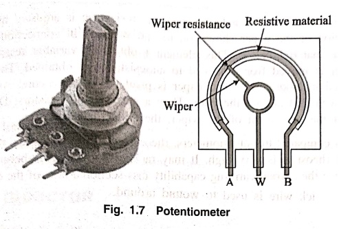
1. Potentiometers
As mentioned in
previous sections, variable resistors are often used to control voltage or
current. Potentiometers is one of the most popular types of variable resistors.
A Potentiometer is simply called as a Pot. This is a three‒terminal resistor
having a shaft which slides or rotates. This shaft when operated forms an
adjustable voltage divider. A potentiometer also measures the potential difference voltage in a circuit. A path
of resistive material with resistance of low to high value is laid internally
and a wiper is placed so that it connects the resistive material to the
circuit. This is mostly used as a volume controller in TV sets and Music
systems.
The following fig. 1.7
shows an image of a Potentiometer.
Out of the three
terminals, two are used. One is connected to the resistive element, and the
other is connected to the knob. As seen in the above figure, by rotating the
knob above, the position of the resistance differs. We know that resistance
depends on the area of cross‒section, length, and specific resistance. So by
varying the position of the knob, the length varies and hence resistance
varies.
This change in the
resistance cause change in voltage, and hence the potential difference. A
simple example of this potentiometer is changed in the speed of the ac motor by
applying a varied armature voltage. They are also frequently used as power
control devices. They can control voltage, current. Light intensity, sound,
etc. Also used in heaters, oven, electric motors, and many other electrical
appliances.
They are preferred in
applications where voltage control is required. There are mainly two groups of
potentiometers known as mechanical and digital. Mechanical potentiometers such
as linear and rotary potentiometers have accuracy problems in vibrational
circumstances. Digital potentiometers are commonly used due to sensitivity
problem of mechanical potentiometers. One of the most fundamental uses of
digital potentiometers is to come up with resistance drift problem that occurs
in challenging environmental conditions. Since digital potentiometers can be
adjusted by communication protocols such as I2C, they are also quite
useful in cases where mechanical resistance adjustment isn't possible.
2. Rheostats
The construction of a
rheostat is similar to that of a potentiometer. However, the rheostat's moving
terminal is short circuited with one of the side terminals as shown in Fig.
1.8. Rheostats are preferred in applications where resistance adjustment or
current limitation required.
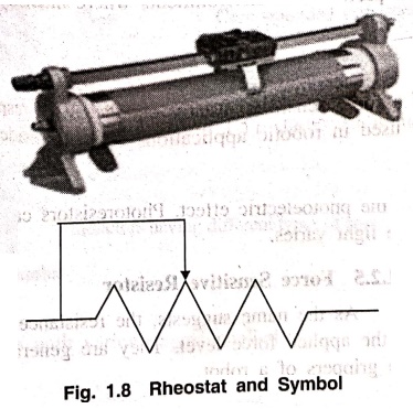
This is also called a linear
rheostat. In this type, the resistance is adjusted by varying the position of
the wiper shown on the horizontal bar. The wiper is in connection with the
resistance material below. This element has two ends for obtaining variable
resistance. As the wiper is moved from one end to another, a variable
resistance is obtained. This type is often used in laboratories. The wiper is
placed a top an insulated ceramic core. And a long wire is wounded around the
core. They are also called as wire wound resistors. Due to the nature of the
movement of the wiper, they are also called slide rheostats.
As compared to
potentiometers, rheostats carry more current. In other words, the current
rating of rheostats is very high. It may range up to 10 A. The high rating is because
of the wire. Since the current‒carrying capability depends on the cross‒sectional
area of the conductor, to carry high currents, the thick wire is used to wound
around.
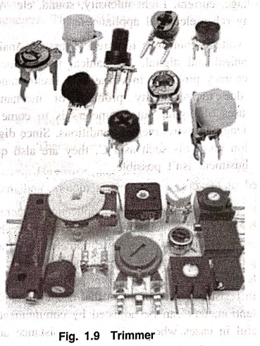
3. Trimmer
Trimmer is both a
variable resistor and a potentiometer measures potential difference measures
potential difference. This Trimmer Potentiometer is, in short called as Trim Pot. If these are used as variable
resistors, then they are called as Preset Resistors.
4. Photoresistors
Photoresistors also
known as light dependent resistors (LDRs) are a common type of variable
resistor. Their resistance changes with respect to the intensity of incoming
light due to the photoelectric effect. Photoresistors can be preferred in
environments where intensity of the light varies.
5. Force Sensitive Resistor
As the name suggests,
the resistance of a force sensitive resistor changes with respect to the
applied force level. They are generally used in robotic applications such as
inside of the grippers of a robot.
Applications of Variable Resistors
Variable resistors are
found in many of the devices/electronics we have in our homes.
Some of these include
radios, speakers, microphones, TVs, oscillators, smart home control devices
etc. Potentiometers are generally used in home electronic appliances where
speed or volume level control needed.
• Rheostats are used
where current or resistance levels should be adjusted. A common example is the
dimming of lights. In summary, variable resistors are popular in applications
where voltage control or current adjustment required.
Basic Electronics and Electrical Engineering: Chapter 1: Basic Electronics : Tag: Basic Engineering : Fixed and Variable Resistors | Types, Specification, Symbol, Units, Color Coding, Example Problems, Construction, Applications - Resistors
Basic Electronics and Electrical Engineering: Chapter 1: Basic Electronics
Under Subject

Basic Electronics and Electrical Engineering
EE25C04 1st Semester ECE Dept | 2025 Regulation | 2nd Semester 2025 Regulation
Related Subjects

English Essentials I
EN25C01 1st Semester | 2025 Regulation | 1st Semester 2025 Regulation

தமிழர் மரபு - Heritage of Tamils
UC25H01 1st Semester | 2025 Regulation | 1st Semester 2025 Regulation

Applied Calculus
MA25C01 Maths 1 M1 - 1st Semester | 2025 Regulation | 1st Semester 2025 Regulation

Applied Physics I
PH25C01 1st Semester | 2025 Regulation | 1st Semester 2025 Regulation

Applied Chemistry I
CY25C01 1st Semester | 2025 Regulation | 1st Semester 2025 Regulation

Makerspace
ME25C04 1st Semester | 2025 Regulation | 1st Semester 2025 Regulation

Computer Programming C
CS25C01 1st Semester | 2025 Regulation | 1st Semester 2025 Regulation

Computer Programming Python
CS25C02 1st Semester | 2025 Regulation | 1st Semester 2025 Regulation

Fundamentals of Electrical and Electronics Engineering
EE25C03 1st Semester | 2025 Regulation | 1st Semester 2025 Regulation

Introduction to Mechanical Engineering
ME25C03 1st Semester | 2025 Regulation | 1st Semester 2025 Regulation

Introduction to Civil Engineering
CE25C01 1st Semester Civil Department | 2025 Regulation | 1st Semester 2025 Regulation

Essentials of Computing
CS25C03 1st Semester - AID CSE IT Department | 2025 Regulation | 1st Semester 2025 Regulation

Applied Physics I Laboratory
PH25C01 1st Semester practical Laboratory Manual | 2025 Regulation | 1st Semester Laboratory 2025 Regulation

Applied Chemistry I Laboratory
CY25C01 1st Semester practical Laboratory Manual | 2025 Regulation | 1st Semester Laboratory 2025 Regulation

Computer Programming C Laboratory
CS25C01 1st Semester practical Laboratory Manual | 2025 Regulation | 1st Semester Laboratory 2025 Regulation

Computer Programming Python Laboratory
CS25C02 1st Semester practical Laboratory Manual | 2025 Regulation | 1st Semester Laboratory 2025 Regulation

Engineering Drawing
ME25C01 EEE Mech Dept | 2025 Regulation | 2nd Semester 2025 Regulation
Basic Electronics and Electrical Engineering
EE25C04 1st Semester ECE Dept | 2025 Regulation | 2nd Semester 2025 Regulation