Basic Electronics and Electrical Engineering: Chapter 1: Basic Electronics
Inductor
Symbols, Units, Types, Working Principle
Inductor is a passive two‒terminal component that temporarily stores energy in the form of a magnetic field. It is usually called as a coil.
INDUCTOR
Inductor is a passive
two‒terminal component that temporarily stores energy in the form of a magnetic
field. It is usually called as a coil.
The main property of an inductor is that it opposes any change in current.
According to the
Faraday's law of Electromagnetic induction, When the current flowing through an
inductor changes, the time‒varying magnetic field induces a voltage in the
conductor. According to lens law, the direction of induced EMF opposes the change
in current that created it. Hence, induced
EMF is opposite to the voltage applied across the coil. This is the
property of an inductor.
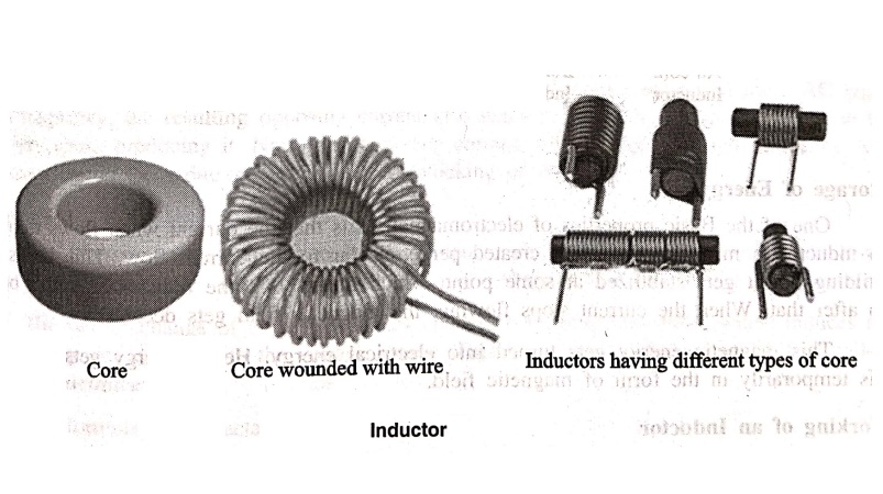
An inductor blocks any
AC component present in a DC signal. The inductor is sometimes wrapped upon a
core, for example a ferrite core. It then looks as in the Fig. 1.10.

The following figure
1.11 shows an inductor with various parts labelled.

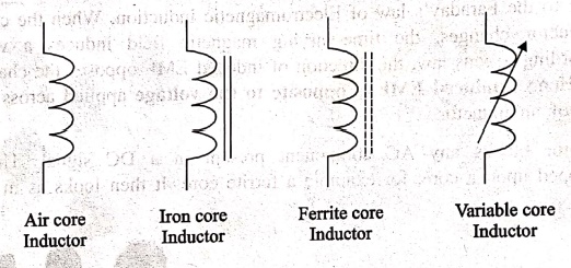
Symbols
The symbols of various
types of inductors are as given below.
Storage of Energy
One of the Basic
properties of electromagnetism is that the current when flows through an
inductor, a magnetic field gets created perpendicular to the current flow. This
keeps on building up. It gets stabilized at some point, which means that the
inductance won't build up after that. When the current stops flowing, the
magnetic field gets decreased.
This magnetic energy
gets turned into electrical energy. Hence energy gets stored in this
temporarily in the form of magnetic field.
Working of an Inductor
According to the theory
of Electromagnetic Induction, any varying electric current, flowing in a
conductor, produces a magnetic field around that, which is perpendicular to the
current. Also, any varying magnetic field, produces current in the conductor
present in that field, whereas the current is perpendicular to the magnetic
field.
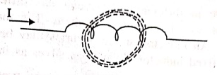
Now, if we consider an
inductor which is made up of a conducting coil and when some current passes
through the inductor, a magnetic field is created perpendicular to it. The following
figure indicates an inductor with magnetic field around it.
Now, here we have a
varying magnetic field, which creates some current through the conductor. But
this current is produced such that it opposes the main current, which has
produced the magnetic field.
If this current is
named as Im which means the current produced due to the magnetic field and the
magnetic field is indicated by β, the following figure indicates it.

This opposing current
gains strength with the varying magnetic field, which gains energy by the input
supply frequency. Hence as the input current becomes more and more AC with high
frequency, the resulting opposing current also gains its strength in opposite
direction to the very cause producing it. Now, this opposing current, tries to
stop the high frequency AC to pass through the inductor, which means
"blocking of AC".
Inductance
The property of an
inductor to get the voltage induced by the change of current flow, is defined
as Inductance. Inductance is the ratio of voltage to the rate of change of
current.
The rate of change of
current produces change in the magnetic field, which induces an EMF in opposite
direction to the voltage source. This property of induction of EMF is called as
the Inductance.
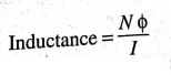
The formula for
inductance is
Inductance = Nϕ / I
Units
The unit of Inductance
is Henry. It is indicated by L.
The inductors are mostly
available in (mH) milliHenry and (μH) microHenry.
A coil is said to have
an inductance of one Henry when an
EMF of one volt is self‒induced in
the coil where the current flowing changed at a rate of one ampere per second.
Inductors are available
in different shapes and has different uses. Their sizes vary depending upon the
material used to manufacture them. The main classification is done as fixed and
variable inductors. An inductor of few Henries may be in a dumbbell shape at
the size of a simple resistor. A fixed inductor always has silver as its first
color in color coding.
The Core of the
Inductor is its heart. There are many types of Inductors according to the core
material used. Let us have a look at a few of them.
1. Air‒core Inductor
The commonly seen
inductor, with a simple winding is this air‒Core Inductor. This has nothing but
air as the core material. The non‒magnetic
materials like plastic and ceramic are also used as core materials and they
also come under this air‒core Inductors. The following figure 1.12 shows
various air‒core inductors.
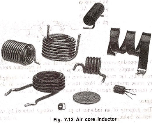
These Inductors offer a
minimum signal loss at the applications having a very high magnetic field
strength. Also, there exists no core losses as there is no solid core material.
2. Iron‒Core Inductor
These Inductors have
Ferromagnetic materials, such as ferrite or iron, as the core material. The
usage of such core materials helps in the increase of inductance, due to their
high magnetic permeability. Permeability
measures the ability of supporting the formation of magnetic fields within the
materials. The following figure 1.13 shows how an Iron‒core Inductor looks like
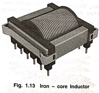
The inductors that have
ferromagnetic core materials just like these, suffer from core losses and
energy losses at high frequencies. These Inductors are used in the manufacture
of few types of transformers.
3. Toroidal Inductors
These Inductors have a
magnetic material as the core substance to which the wire is wound. These are
in circular ring shape, just as shown in the following figure 1.14.
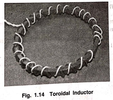
The main advantage of
this type of inductors is that, due to the circular shape, symmetry is achieved
in the whole shape of the inductor, due to which there are minimum losses in
the magnetic flux. These inductors are mostly used in AC circuit applications.
4. Laminated Core Inductors
These are the inductors
that have laminated thin steel sheets, such as stacks, as the core materials.
Usually for an inductor, if the loop area is increased for the current to
travel, the energy losses will be more. Whereas, in these laminated core
Inductors, thin steel sheets of stacks are helpful in blocking the eddy
currents, which minimize the loop action.
The following figure
1.15 shows an image of a laminated core inductor.
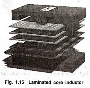
The main advantage of
these inductors is minimizing the energy loss with its construction. These
laminated core inductors are mostly used in the manufacture of transformers.
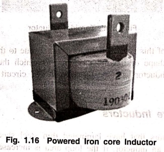
5. Powdered Iron Core Inductors
As the name implies,
the core of these inductors have magnetic materials with some air gaps in it.
But this kind of construction provides an advantage to the core, to store high
level of energy compared with the other types. The following figure 1.16 shows
an image of a Powdered Iron core Inductor.
These inductors provide
very low eddy current losses and hysteresis losses. These are available at
lowest prices and have very good inductance stability.
Basic Electronics and Electrical Engineering: Chapter 1: Basic Electronics : Tag: Basic Engineering : Symbols, Units, Types, Working Principle - Inductor
Basic Electronics and Electrical Engineering: Chapter 1: Basic Electronics
Under Subject

Basic Electronics and Electrical Engineering
EE25C04 1st Semester ECE Dept | 2025 Regulation | 2nd Semester 2025 Regulation
Related Subjects

English Essentials I
EN25C01 1st Semester | 2025 Regulation | 1st Semester 2025 Regulation

தமிழர் மரபு - Heritage of Tamils
UC25H01 1st Semester | 2025 Regulation | 1st Semester 2025 Regulation

Applied Calculus
MA25C01 Maths 1 M1 - 1st Semester | 2025 Regulation | 1st Semester 2025 Regulation

Applied Physics I
PH25C01 1st Semester | 2025 Regulation | 1st Semester 2025 Regulation

Applied Chemistry I
CY25C01 1st Semester | 2025 Regulation | 1st Semester 2025 Regulation

Makerspace
ME25C04 1st Semester | 2025 Regulation | 1st Semester 2025 Regulation

Computer Programming C
CS25C01 1st Semester | 2025 Regulation | 1st Semester 2025 Regulation

Computer Programming Python
CS25C02 1st Semester | 2025 Regulation | 1st Semester 2025 Regulation

Fundamentals of Electrical and Electronics Engineering
EE25C03 1st Semester | 2025 Regulation | 1st Semester 2025 Regulation

Introduction to Mechanical Engineering
ME25C03 1st Semester | 2025 Regulation | 1st Semester 2025 Regulation

Introduction to Civil Engineering
CE25C01 1st Semester Civil Department | 2025 Regulation | 1st Semester 2025 Regulation

Essentials of Computing
CS25C03 1st Semester - AID CSE IT Department | 2025 Regulation | 1st Semester 2025 Regulation

Applied Physics I Laboratory
PH25C01 1st Semester practical Laboratory Manual | 2025 Regulation | 1st Semester Laboratory 2025 Regulation

Applied Chemistry I Laboratory
CY25C01 1st Semester practical Laboratory Manual | 2025 Regulation | 1st Semester Laboratory 2025 Regulation

Computer Programming C Laboratory
CS25C01 1st Semester practical Laboratory Manual | 2025 Regulation | 1st Semester Laboratory 2025 Regulation

Computer Programming Python Laboratory
CS25C02 1st Semester practical Laboratory Manual | 2025 Regulation | 1st Semester Laboratory 2025 Regulation

Engineering Drawing
ME25C01 EEE Mech Dept | 2025 Regulation | 2nd Semester 2025 Regulation
Basic Electronics and Electrical Engineering
EE25C04 1st Semester ECE Dept | 2025 Regulation | 2nd Semester 2025 Regulation