Basic Electronics and Electrical Engineering: Chapter 6: Measurement and Instrumentation
Cathode Ray Oscilloscope
Construction, Structure Blocks, Working Principle
The cathode ray oscilloscope is a device that allows the amplitude of electrical signal, whether they be voltage, current, power and etc, to be displayed primarily as a function of time.
CATHODE
RAY OSCILLOSCOPE
The cathode ray
oscilloscope is a device that allows the amplitude of electrical signal,
whether they be voltage, current, power and etc, to be displayed primarily as a
function of time. The oscilloscope depends on the movement of an electron beam,
which is then made visible by allowing the beam to impinge on a phosphor
surface, which produces a visible spot. If the electron beam is deflected in
either of two orothogonal axes, such as the familiar X and Y axes used in
conventional graph construction, the luminous spot can be used to create two‒dimensional
displays.
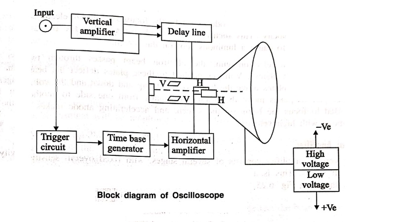
Various blocks and Working of Oscilloscope
The major block circuit
of general purpose CRO is shown in Fig. 6.23.

1. Cathode Ray Tube
A CRO consists of
cathode ray tube (CRT) which is the heart of the oscilloscope, and some
additional circuitry to operate the CRT. The major parts of the CRT are
(i) Electron gun
assembly
(ii) Deflection plate
assembly
(iii) Fluorescent
screen
(iv) Glass envelope
The cathode ray tube is
shown in fig. 6.24.
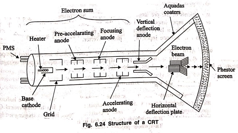
The electron gun
assembly produces a shortly focused beam of electrons which are accelerated to
high velocity. This focused beam of electrons strikes the fluorescent screen with
sufficient energy to cause a luminous spot on the screen.
After leaving the
electron gun, the electron beam passes through two pairs of "Electrostatic
deflection plates". Voltages applied to these plates deflect the beam.
Voltages applied to one pair of plates move the beam vertically up and down and
the voltages applied to the other pair of plates move the beam horizontally
from one side to another. Focusing anode is used to focus the beam on the
screen, and accelerating anode makes the electron beam to move with high
velocity.
2. Vertical Amplifier
The vertical amplifier
consists of several stages, with fixed overall sensitivity or gain expressed in
v/divs. This is a wide band amplifier used to amplify signals in the vertical
section as shown in Fig. 6.25.
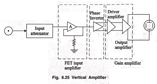
The first elements of
the pre amplifier is the input stage, often consisting a FET source amplifier
whose high input impedance isolates the amplifier from the attenuator. The FET
input stage is followed by a BJT emitter follower to match the medium impedance
of FET output with the low impedance input of the phase inverter.
The phase inverter
provides two antiphase output signals which are required to operate the
pushpull output amplifier. The push pull output stage delivers equal signal
voltages of opposite polarity to the vertical plates of the CRT.
3. Delay line, Horizontal and Vertical deflection circuit
Delay line is used to
delay the signal for some time in the vertical section. The horizontal signal
is initiated or triggered, by a portion of the output signal applied to the
vertical CRT plates. Signal processing in the horizontal channel consists of
generating and shaping a trigger pulse that starts the sweep generator; whose
output is fed to the horizontal amplifier and then to horizontal deflection
plates. This whole process takes time in the order of 80 ns. To allow the
operator to observe the leading edge of the signal waveform, the signal drive
fore the vertical CRT plates must therefore be delayed by atleast the same
amount time. It is fixed by delay line.
4. Horizontal Amplifiers
The horizontal
amplifier basically serves two purposes.
(i) When the
oscilloscope is used in the X‒Y mode, the signal applied to the horizontal
input‒terminal will be amplified by the horizontal amplifier.
(ii) When the
oscilloscope is used in the ordinary mode of operation to display a signal
applied to the vertical input, the horizontal amplifier will amplify the sweep
generator output.
5. Time base Generator
It is used to generate
the saw tooth voltage required to deflect the beam in the horizontal section.
6. Trigger Circuit
This is used to convert
the incoming signal into the trigger pulses that the input signal and the sweep
frequency can be synchronized.
7. Power Supply
Power supply circuit
has two power supplies, a negative high voltage (HV) supply and a positive low
voltage (LV) supply. Two voltages are generated in the CRO. The positive voltage
supply is from +300 to 400V. The negative high voltage supply from ‒ 100 to ‒1500
V. This voltage is passed through a bleeder resistor at a few mA.
Basic Electronics and Electrical Engineering: Chapter 6: Measurement and Instrumentation : Tag: Basic Engineering : Construction, Structure Blocks, Working Principle - Cathode Ray Oscilloscope
Basic Electronics and Electrical Engineering: Chapter 6: Measurement and Instrumentation
Under Subject

Basic Electronics and Electrical Engineering
EE25C04 1st Semester ECE Dept | 2025 Regulation | 2nd Semester 2025 Regulation
Related Subjects

English Essentials I
EN25C01 1st Semester | 2025 Regulation | 1st Semester 2025 Regulation

தமிழர் மரபு - Heritage of Tamils
UC25H01 1st Semester | 2025 Regulation | 1st Semester 2025 Regulation

Applied Calculus
MA25C01 Maths 1 M1 - 1st Semester | 2025 Regulation | 1st Semester 2025 Regulation

Applied Physics I
PH25C01 1st Semester | 2025 Regulation | 1st Semester 2025 Regulation

Applied Chemistry I
CY25C01 1st Semester | 2025 Regulation | 1st Semester 2025 Regulation

Makerspace
ME25C04 1st Semester | 2025 Regulation | 1st Semester 2025 Regulation

Computer Programming C
CS25C01 1st Semester | 2025 Regulation | 1st Semester 2025 Regulation

Computer Programming Python
CS25C02 1st Semester | 2025 Regulation | 1st Semester 2025 Regulation

Fundamentals of Electrical and Electronics Engineering
EE25C03 1st Semester | 2025 Regulation | 1st Semester 2025 Regulation

Introduction to Mechanical Engineering
ME25C03 1st Semester | 2025 Regulation | 1st Semester 2025 Regulation

Introduction to Civil Engineering
CE25C01 1st Semester Civil Department | 2025 Regulation | 1st Semester 2025 Regulation

Essentials of Computing
CS25C03 1st Semester - AID CSE IT Department | 2025 Regulation | 1st Semester 2025 Regulation

Applied Physics I Laboratory
PH25C01 1st Semester practical Laboratory Manual | 2025 Regulation | 1st Semester Laboratory 2025 Regulation

Applied Chemistry I Laboratory
CY25C01 1st Semester practical Laboratory Manual | 2025 Regulation | 1st Semester Laboratory 2025 Regulation

Computer Programming C Laboratory
CS25C01 1st Semester practical Laboratory Manual | 2025 Regulation | 1st Semester Laboratory 2025 Regulation

Computer Programming Python Laboratory
CS25C02 1st Semester practical Laboratory Manual | 2025 Regulation | 1st Semester Laboratory 2025 Regulation

Engineering Drawing
ME25C01 EEE Mech Dept | 2025 Regulation | 2nd Semester 2025 Regulation
Basic Electronics and Electrical Engineering
EE25C04 1st Semester ECE Dept | 2025 Regulation | 2nd Semester 2025 Regulation