Basic Electronics and Electrical Engineering: Chapter 6: Measurement and Instrumentation
Moving Iron [MI] Instruments
Types, Construction, Operation principles, Errors, Advantages, Limitations, Comparison
1. Types of MI Instruments 2. Operation principles of MI Instruments.. 3. Errors in MI Instruments 4. Advantages and Limitations of MI Instruments 5. Comparison between PMMC and MI Instruments 6. Extension of Instrument Range
MOVING
IRON [MI] INSTRUMENTS
Types of MI Instruments
All moving iron
instruments may be classified, under the following two major groups.
They are:
1. Attraction type
2. Repulsion type
1. Attraction Type
Construction
A moving iron, wended
on a spindle, is situated inside a coil of wire. The moving iron is CAM shaped
and consists of two or three thin discs of soft iron. It is eccentrically which
pivoted on the spindle. The spindle carries a pointer which moves over a
graduated scale. The spindle is pivotated to jewelled bearings. The
construction detail is shown in fig (6.8).
Working
The coil of wire be
connected in series with the circuit if the instrument is an ammeter or in
parallel, if it is a voltmeter. If an ammeter, the coil will carry either the
load current or a definite fraction of it. If a voltmeter, the coil will carry
a current proportional to the voltage across the circuit. In both cases a
magnetic field will be set up inside the coil. The soft iron piece is,
therefore, attracted and so it tends to move from the weaker magnetic field
outise the coil, to the stronger field inside it. Since the moving is
eccentrically pivoted the spindle is turned and so the pointer deflects.
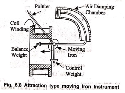
Controlling and Damping
Spring control is
almost universally used, but gravity control can be used in panel type
instruments which are vertically mounted. A hair spring, made of phosphor
bronze, is attached to the spindle so that when the spindle turns, the spring
test coiled and exerts a controlling torque. Damping is by air friction. A
piston, attached to the spindle, moves inside an air chamber and gives the
necessary damping.
2. Repulsion Type
In repulsion type of
moving iron instruments, there are two vanes inside the coil, one fixed and the
other moveable. These are similarly magnetised when current flows through the
coil. So there is a force of repulsion between the two vanes resulting in the
movement of the moving vane.
There are two different
types in repulsion type instruments. They are,
(i) Radial vane type
(ii) Co‒axial vane type
(i) Radial vane type instrument
The Fig. 6.9 shows the
radial vane repulsion type instrument. Out of the other moving iron mechanisms,
this is the most sensitive and has most linear scale.
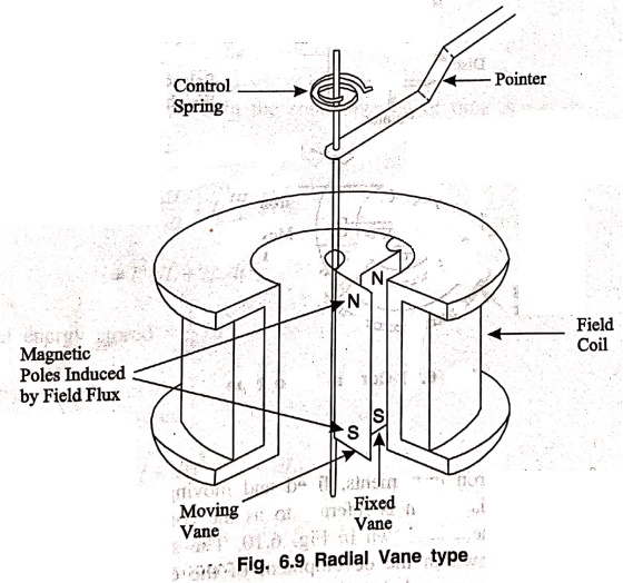
Construction
There will be two vanes
which are the fixed and movable vanes. The fixed vane will be attached to the
coil. Whereas movable vane is attached to the spindle and suspended in the
induction field of the coil. The needle of the instrument is attached to this
vane.
Working
Eventhough the current
through the coil is alternating, there is always repulsion between the like
poles of the fixed and the movable vane. Hence the deflection of the pointer is
always in the same direction. The deflection is effectively proportional to the
actual current and hence the scale is calibrated directly to read amperes or
volts. The calibration is accurate only for the frequency for which it is
designed because the impedance is different for different frequencies.
(ii) Coaxial vane type instrument

Construction
In this form of
repulsion iron instruments, fixed and moving vanes are used, which are sections
of co‒axial cylinders. This design is referred to as the concentric‒vane or
coaxial‒vane form of instrument. The arrangement is shown in Fig. 6.10. The
stationary and moving vanes have shapes similar to those shown in the
development of the cylinders. The fixed vane made tongue shaped to obtain more
or less uniform scale.
Working
The current in the coil
sets up a magnetic field inside the coil, where the fixed vane and moving vane
are situated. Since both the irons are influenced by the same magnetic field, they
are similarly magnetized. Hence the moving vane is repelled from the fixed
vane, so the spindle turns and the pointer deflects.
(iii) Torque Equation of moving Iron Instruments
Let,
I= initial current in
the coil.
ϕ= angle of deflection
dϕ = change in
deflection
dl = Increase in current in the coil
dL = change in
inductance
The change in voltage
due to change in current,
e = d/dt (LI)
= I dL/dt + L dI/dt ………..(6.1)
Electrical energy
supplied in the small interval of time dt = eI dt ………..(6.2)
Substituting eqn (1) in
(2) we get
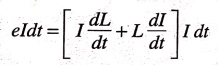
= I2 dL + IL
dt
Initial energy stored =
1/2 LI2.
………..(6.4)
Energy stored after the
current is measured
dI = ½ (I + dI)2 * (L+ dL) ………..(6.5)
= 1⁄2 (I2 + 2IdI
+ dI2) (L + dL)
Change in stored energy
= ½(I2+2IdI+dI2)(L+dL) ‒ ½I2L.
= ½(I2L+2ILdI+LdI2)
+ ½(I2dL +2IdIdL+dI2dL) ‒ ½I2L.
= ILdI + ½Ldl2
+ ½I2dL + IdIdL
+ ½dI2dL
Neglecting second and
higher order terms, since they are comparatively very small, then the above
equation becomes.
= ILdI + ½I2dL …………(6.6)
Mechanical work done =
Td dθ
…………(6.7)
From the principle of
conservation of energy,
Electrical energy
supplied = Increase in stored energy + Mechanical work done
From eqn. (3), (6) and
(7) we get.
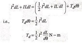
We know, Tc
= Sθ
At equilibrium
position,
Tc = Td
KSθ = 1/2 .
I2 . dL/dθ
KSθ = 1/2 .
I2/KS . dL/dθ
Since Td ∝ I2 it can
be used for measurement of both DC and AC,
(iv) Reason for using a MI Instrument on both AC and DC
The deflection ϕ, in
moving iron instruments is proportional to the square of the operating current.
From this, it is evident that the deflection is always positive. That is, the
iron vanes are so magnetised that there is always a force of attraction in case
of attraction type and repulsion in case of repulsion type independent of the
direction of current. The moving iron instruments are unpolarized instruments
i.e., instruments which are independent of the direction in which current
passes through them. And also MI instruments read the RMS value of the current
or voltage. In DC the RMS value is equal to average value. Therefore these
instruments can used on both AC and DC.
Operation principles of MI Instruments
In this type of
instrument, the coil is fixed through which current passes. The moving iron is
a flat disc, which is mounted between the fixed coils. When the current passes
through the coil, the moving iron is moved either by force of attraction or
repulsion.
Errors in MI Instruments
There are two types of
errors which occurs in moving iron instruments. They are,
1. Errors which occurs
with both AC and DC.
2. Errors which occurs
with AC only.
1. Errors with both AC and DC
i)
Hystersis
Moving iron instruments
tends to read higher for descending values of current (voltage) than for
ascending values. This is due to the hysteresis effect of the ion parts. That
is the value of flux density is different for the same value of current when
ascending and descending.
This error can be
minimised by making the parts small so that they demagnitize themselves
quickly.
ii)
Temperature Error
The effect of
temperature changes on MI instrument arises, chiefly from the temperature co-efficient
of spring. The error may be 0.02 percent per °C. For voltmeter both the temperature
co-efficient of spring and temperature co‒efficient of voltmeter may balance
each other.
iii)
Strong magnetic fields
The errors due to stray
magnetic fields may be appreciable as the operating magnetic field is weak and
hence can be easily distorted. Such errors depend upon the direction of the
stray magnetic field relating to the field of instrument. These errors can be
minimised by using an iron case or a thin iron shield over the working parts.
2. Errors with AC only
(i)
Frequency errors
Changes in frequency
cause errors due to change of resistance of the working coil and also due to
changes of magnitude of eddy currents set up in the metal parts of instruments.
(ii)
Error due to reactance
The change of reactance
of instrument coil is important in case of voltmeters where an additional
resistance RS is used in series with the instrument coil. This error
may be compensated by connecting a suitable capacitor across the series
resistance.
(iii)
Error due to eddy current
Eddy current errors are
caused due to mutual inductance between the working coil and the metal parts.
At low frequencies the eddy current error increases with square of the
frequency and at high frequencies the error is practically constant. For these
reasons MI instruments are unsuitable for frequencies above 100 Hz.
Advantages and Limitations of MI Instruments
Advantages
1.
Universal use
These instruments can
be used for both AC and DC.
2.
Less Friction Errors
Errors due to friction
are quite small as torque/weight ratio is quite high in these instruments.
3.
Cheapness
The fact that a single
type of moving element could cover the entire range is one reason, that M.I
instruments can be built at less cost than other types.
4.
Robustness
These instruments are
robust owing to simple construction and also that there are no current carrying
moving parts.
5.
Accuracy
These instruments are
capable of giving an accuracy within the limits of precision and industrial grades.
6.
Scale
Moving iron instruments
are now available with 240° circular scales. The increased scales length being
a certain advantage.
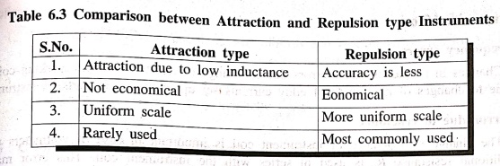
Limitations
1. The scale of M.I
instrument is not uniform and is cramped at the lower end and therefore
accurate readings are not possible at this end.
2. Errors: These
instruments are subjected to serious errors due to hysteresis, frequency
changes and stray magnetic fields.
Comparison between PMMC and MI Instruments

PMMC Instruments
1. Moving system
carries the operating current.
2. Permanent magnet is
used to produce the magnetic field required.
3. Spring control is
used.
4. Eddy current
damping.
5. Deflecting Torque is
proportional to the operating current, Td ∝ I.
6. Uniform scale.
7. Polarised
8. Read the average
value.
9. Magnetic shielding
is not required.
10. No hysteresis
error.
11. Costlier than M.I
but cheaper than Dynamometer type.
MI Instruments
1. Moving system does
not carry the operating current.
2. Electro‒magnetic
field is used.
3. Gravity control is
used.
4. Air friction
damping.
5. Td is
proportional to the square of the operating current, Td ∝ I2.
6. Non-uniform scale.
7. Unpolarised
8. Reads the rms value.
9. It has to be
shielded.
10. Hysterisis error
will occur in AC measurement.
11. Cheapest
Extension of Instrument Range
1. Extension of current range for coil ammeters
An ammeter shunt is
merely a low resistance that is placed in parallel with the coil circuit of the
instrument in order to measure fairly large current. The greater part of
current in main circuit is diverted through the shunt. The circuit diagram for
a shunt and milli‒ampere meter for measuring large currents is shown in Fig.
6.11.
The main circuit
current I will split into two parts. Im is the low current flowing
through the ammeter and Ish is the heavy current is flowing through
the shunt.
Construction of Shunt
Shunt for lower current
range can be housed inside the instrument case but above 200 amps the shunts
are provided outside the meter.
The shunts used in dc
instruments. The temperature co‒efficient of resistance must be very low and as
far as possible equal to that of the instrument coil so that multiplying power of
the shunt shall be independent of temperature. The resistance of the shunt
should not vary with the time of usage. The thermo electric emf of the shunt
should be very small and it must be capable of carrying required current
without appreciable heating.
The shunt material is
usually manganic in order that the resistance changes due to change in
temperature may be small as possible, and also low thermo‒electric emf with
copper.

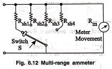
Multi‒range Ammeters
The current range of DC
ammeter, may be further extended by a number of shunts selected by a range
switch for the measurement of different current of full scale deflection in the
meter. Such meter is called a multi range ammeter.
The Fig. 6.12 shows the
circuit diagram of multirange ammeter. The circuit has for shunts Rsh1,
Rsh2, Rsh3 and Rsh4 are connected in parallel
with the meter to give 4 different current ranges I1, I2,
I3 and I4. Sometimes when larger current are measured,
the connections are brought out to terminal post which is marked for different
current ranges 10, 25, 50 amps etc. These ranges are used first from highest
current range to the lowest range to avoid the damage of the meter when unknown
value of the current is measured.
2. Extension of voltage range for moving coil voltmeters

A millivoltmeter may be
converted into voltmeter to the ranges of 100 V, 150 V, 250 V, 500 volts etc.,
by connecting a series resistance in it is shown in fig (6.13). This series
resistance and the coil is connected in series and put across the circuit whose
voltage is to be measured. The multiplier limits the current through the meter
so that it does not exceed the value for full scale deflection and prevents the
damage of coil.
Construction of Multipliers
The essential
requirements of multiplier are
1. their resistance
should not change with time.
2. they should be non‒inductive
type when it is used in ac supply.
3. Low thermo‒electric
emf with copper. The material used for multipliers are mangenin etc.,
The common method of
winding non‒inductive resistance is the bifilar winding. The bifilar winding is
made by taking wire in double wound. For single range voltmeter, the series
resistance is bifilar winding.
For multi‒range
voltmeter a high resistance of single layer winding is wound on a thin mica or
other insulating card. Multipliers case for voltages upto 500 volts for higher
voltage the multiplier may be mounted separately outside the case to avoid
excessive heating inside the case.
Multi‒range voltmeter
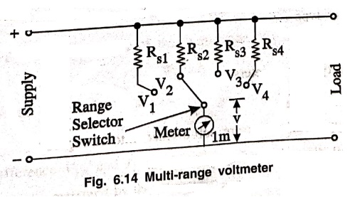
The multirange
voltmeter is shown in fig (6.14) in which the connections are made at the
junctions of resistances R1, R2, R3 and R4
in series to obtain the voltage ranges V1, V2, V3
and V4. These connection are brought out to terminal post on the
instrument and the instrument is connected to the proper desired level range.
The series resistance for the voltage ranges V1, V2, V3
and V4 can be calculated.
Basic Electronics and Electrical Engineering: Chapter 6: Measurement and Instrumentation : Tag: Basic Engineering : Types, Construction, Operation principles, Errors, Advantages, Limitations, Comparison - Moving Iron [MI] Instruments
Basic Electronics and Electrical Engineering: Chapter 6: Measurement and Instrumentation
Under Subject

Basic Electronics and Electrical Engineering
EE25C04 1st Semester ECE Dept | 2025 Regulation | 2nd Semester 2025 Regulation
Related Subjects

English Essentials I
EN25C01 1st Semester | 2025 Regulation | 1st Semester 2025 Regulation

தமிழர் மரபு - Heritage of Tamils
UC25H01 1st Semester | 2025 Regulation | 1st Semester 2025 Regulation

Applied Calculus
MA25C01 Maths 1 M1 - 1st Semester | 2025 Regulation | 1st Semester 2025 Regulation

Applied Physics I
PH25C01 1st Semester | 2025 Regulation | 1st Semester 2025 Regulation

Applied Chemistry I
CY25C01 1st Semester | 2025 Regulation | 1st Semester 2025 Regulation

Makerspace
ME25C04 1st Semester | 2025 Regulation | 1st Semester 2025 Regulation

Computer Programming C
CS25C01 1st Semester | 2025 Regulation | 1st Semester 2025 Regulation

Computer Programming Python
CS25C02 1st Semester | 2025 Regulation | 1st Semester 2025 Regulation

Fundamentals of Electrical and Electronics Engineering
EE25C03 1st Semester | 2025 Regulation | 1st Semester 2025 Regulation

Introduction to Mechanical Engineering
ME25C03 1st Semester | 2025 Regulation | 1st Semester 2025 Regulation

Introduction to Civil Engineering
CE25C01 1st Semester Civil Department | 2025 Regulation | 1st Semester 2025 Regulation

Essentials of Computing
CS25C03 1st Semester - AID CSE IT Department | 2025 Regulation | 1st Semester 2025 Regulation

Applied Physics I Laboratory
PH25C01 1st Semester practical Laboratory Manual | 2025 Regulation | 1st Semester Laboratory 2025 Regulation

Applied Chemistry I Laboratory
CY25C01 1st Semester practical Laboratory Manual | 2025 Regulation | 1st Semester Laboratory 2025 Regulation

Computer Programming C Laboratory
CS25C01 1st Semester practical Laboratory Manual | 2025 Regulation | 1st Semester Laboratory 2025 Regulation

Computer Programming Python Laboratory
CS25C02 1st Semester practical Laboratory Manual | 2025 Regulation | 1st Semester Laboratory 2025 Regulation

Engineering Drawing
ME25C01 EEE Mech Dept | 2025 Regulation | 2nd Semester 2025 Regulation
Basic Electronics and Electrical Engineering
EE25C04 1st Semester ECE Dept | 2025 Regulation | 2nd Semester 2025 Regulation