Basic Electronics and Electrical Engineering: Chapter 6: Measurement and Instrumentation
Instrument Transformer
Types, Working Principle, Advantages and Disadvantages
1. Types of Instrument Transformer 2. Advantages and Disadvantages of Instrument Transformer
INSTRUMENT
TRANSFORMER
We have studied
earlier, that a low‒range ammeter can be used to measure a high value current
by using shunts. Similarly, the measuring range of a voltmeter can be extended
by using multipliers. However, there are some limitations to use of shunts and
multipliers for measurement of high current and high voltage respectively by
using low‒range ammeters and voltmeters.
For measurement of high
current and high voltage, voltmeters and ammeters of higher ranges are not
used. Instead, for such measurement current transformers (CT) and potential
transformers (PT) are used along with low range ammeters and voltmeters.
Transformers used for measurement of
current is called current transformer (CT) and the transformer used voltage
measurement is called a voltage transformer or potential transformer (PT)
Types of Instrument Transformer
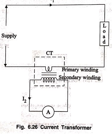
1. Current Transformer (CT)
Generally a transformer
is a device which consists of two windings called primary and secondary and
transfers the energy from one side to another by changing the voltage and
current. Current transformer is a device used to decrease the current level by
stopping up the voltage and keeping the energy as constant. Fig. 6.26. shows
the circuit of a current transformer in which the primary winding of the CT is
connected in series with line carrying the current to be measured and therefore
the primary current is dependent on the load connected to the system whose
current is to be measured. The secondary winding of the CT is connected to the
low range ammeter. As the secondary voltage of CT is higher than the primary
voltage, secondary winding has more number of turns compared to the primary
winding. In case of CT, the secondary current is less than the primary current.
In case of Current
Transformer, n = N2/N1
= I1/I2= V2/V1
Where,
I1 be the
primary current in A
I2 be the
secondary current in A
V1 be the
primary voltage in V
V2 be the
secondary voltage in V
For example, if the
range of CT is 500:5
I1 = 500 A
I2 = 5 A
n = 500/5 = 100
V2/V1
= 100
V2 = 100 V1
From the above
equation, it is noticed that in order to decrease the secondary current by 100
times, the secondary voltage should be decreased by 100 times.
2. Potential Transformer (PT)
Potential transformers
are similar to two winding transformers except that the secondary volt‒amp
loading is very low. The primary winding is the high voltage winding which is
connected across the lines whose voltage is to be measured and the secondary is
connected to the low range voltmeter coil. One end of the secondary winding is
always grounded for safety purpose. Fig. 6.27 shows the circuit of a potential
Transformer.
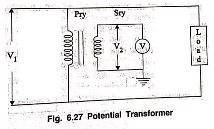
In general potential
transformer acts as step down transformer. The secondary winding voltage of PT
is lesser than the primary voltage. The secondary current of PT is more than
that of primary current. The turns ratio of PT can be expressed as
n = N1/N2
= V1/V2
Advantages and Disadvantages of Instrument Transformer
Advantages
1. High voltage and
high current can be measured using low range voltmeter, ammeter along with the
instrument transformer.
2. The rating of low
range meter can be fixed in respective of the value of high voltage or high
current to be measured.
3. Instrument
transformer ensure the safety of the operator and make the handling of the
equipments very easy.
4. They can be used for
operating many types of protecting devices such as relays or pilot lights.
Disadvantages
Instrument transformers
can be used only for ac circuits and not for dc circuits.
Basic Electronics and Electrical Engineering: Chapter 6: Measurement and Instrumentation : Tag: Basic Engineering : Types, Working Principle, Advantages and Disadvantages - Instrument Transformer
Basic Electronics and Electrical Engineering: Chapter 6: Measurement and Instrumentation
Under Subject

Basic Electronics and Electrical Engineering
EE25C04 1st Semester ECE Dept | 2025 Regulation | 2nd Semester 2025 Regulation
Related Subjects

English Essentials I
EN25C01 1st Semester | 2025 Regulation | 1st Semester 2025 Regulation

தமிழர் மரபு - Heritage of Tamils
UC25H01 1st Semester | 2025 Regulation | 1st Semester 2025 Regulation

Applied Calculus
MA25C01 Maths 1 M1 - 1st Semester | 2025 Regulation | 1st Semester 2025 Regulation

Applied Physics I
PH25C01 1st Semester | 2025 Regulation | 1st Semester 2025 Regulation

Applied Chemistry I
CY25C01 1st Semester | 2025 Regulation | 1st Semester 2025 Regulation

Makerspace
ME25C04 1st Semester | 2025 Regulation | 1st Semester 2025 Regulation

Computer Programming C
CS25C01 1st Semester | 2025 Regulation | 1st Semester 2025 Regulation

Computer Programming Python
CS25C02 1st Semester | 2025 Regulation | 1st Semester 2025 Regulation

Fundamentals of Electrical and Electronics Engineering
EE25C03 1st Semester | 2025 Regulation | 1st Semester 2025 Regulation

Introduction to Mechanical Engineering
ME25C03 1st Semester | 2025 Regulation | 1st Semester 2025 Regulation

Introduction to Civil Engineering
CE25C01 1st Semester Civil Department | 2025 Regulation | 1st Semester 2025 Regulation

Essentials of Computing
CS25C03 1st Semester - AID CSE IT Department | 2025 Regulation | 1st Semester 2025 Regulation

Applied Physics I Laboratory
PH25C01 1st Semester practical Laboratory Manual | 2025 Regulation | 1st Semester Laboratory 2025 Regulation

Applied Chemistry I Laboratory
CY25C01 1st Semester practical Laboratory Manual | 2025 Regulation | 1st Semester Laboratory 2025 Regulation

Computer Programming C Laboratory
CS25C01 1st Semester practical Laboratory Manual | 2025 Regulation | 1st Semester Laboratory 2025 Regulation

Computer Programming Python Laboratory
CS25C02 1st Semester practical Laboratory Manual | 2025 Regulation | 1st Semester Laboratory 2025 Regulation

Engineering Drawing
ME25C01 EEE Mech Dept | 2025 Regulation | 2nd Semester 2025 Regulation
Basic Electronics and Electrical Engineering
EE25C04 1st Semester ECE Dept | 2025 Regulation | 2nd Semester 2025 Regulation