Basic Electronics and Electrical Engineering: Chapter 6: Measurement and Instrumentation
Essential Torques of Indicating Instruments
The moving system is subjected to the following three torques: 1. Deflecting (or operating) torque 2. Controlling (or restoring) torque 3. Damping torque
ESSENTIAL
TORQUES OF INDICATING INSTRUMENTS
Indicating Instruments
are those which indicate the value of the measured quantity at the time at
which it is measured. Such instruments essentially consists a pointer which
moves over a calibrated scale and which is attached to a moving system, pivoted
in a jewelled bearing. The moving system is subjected to the following three
torques:
1. Deflecting (or
operating) torque
2. Controlling (or
restoring) torque
3. Damping torque
1. Deflecting Torque (Td)
This torque (Td)
is produced by utilizing one or more effects mentioned above (ie., magnetic,
electrostatic, electrodynamic, thermal or chemical etc.,) This torque cause the
moving system of the instrument to move from its zero position i.e., its
position when the instrument is disconnected from the supply.
2. Controlling Torque (Tc)
The deflection of the
moving system will be indefinite, unless otherwise controlled by some opposing
torque to make the deflection constant at any particular position for a given
value of quantity being measured on the scale of the dial. Such a torque is
called controlling torque. The magnitude of the controlling torque should
increase with the angle of deviation and the torque should be acting in a
direction, opposite to that of deflecting torque.
With the two torques
acting on the moving system it should come to rest at such a position at which
the controlling torque is equal to the deflecting torque. The controlling
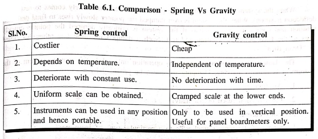
torque in an indicating instrument is always obtained by a spring or much less
by the gravity of the moving system.
1. Spring Control
A hair‒spring, usually
of phosphor‒bronze, is attached to the moving system of the instrument, as
shown in Fig. 6.1 (a).
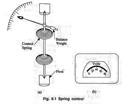
With the deflection of
the pointer, the spring will be twisted in the opposite direction. This twist
in the spring produces controlling torque, which is directly proportional to
the angle of deflection of the moving system Td ∝ I. The pointer comes
to a position of rest, when the deflecting torque (Td) and
controlling torque (Tc) are equal. For example, in permanent‒magnet moving coil
(PMMC) type of instruments, the deflecting torque is proportional to the
current. I passing through them.
∴
Td ∝
I
As,
Tc = Td
θ = I
Since, deflection θ is
directly proportional to current I, the spring‒controlled instruments have an
uniform or equally‒spaced scales over the whole of their range as shown in Fig.
6.1 (b).
The requirements of
spring material:
(i) It should be non‒magnetic.
(ii) Not subjected to
appreciable fatigue.
(iii) Should have low
specific resistance
(iv) Low temperature‒resistance
co‒efficient.
2. Gravity Control
In gravity controlled
instruments, a small adjustable weight is attached to the moving system in such
a way that it produces a controlling torque when the system is deflected. This
is illustrated in the fig (6.2).
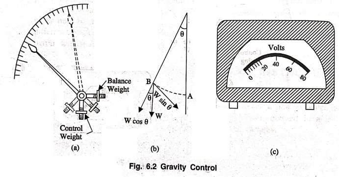
In this controlling
system, the controlling torque is proportional to the sine of angle of
deflection,
Tc ∝ sin θ (Not θ)
If
Td ∝ I
As,
Tc = Td
I = sin θ (Not θ)
Hence in gravity ‒
controlled instruments the scale will not be uniform but are cramped or crowded
at their lower ends.
3. Damping Torque
Even with the existence
of deflecting torque and controlling torque acting on the moving system, it
will not come to the position of rest due to the inertia possessed by it. The
pointer which is attached to the moving system will oscillate about the
equilibrium position, and will come to rest only after a long time. This
involves time and create hardships in observing quick readings and also prevent
another force which is required to dampout the oscillations occurring at the
position of equilibrium for any given quantity of electricity that is being
measured. Hence a third torque known as damping torque is required to act on
the moving system, so as to bring the moving system quickly to the position of
rest without oscillation.
The adjoining curves
shows the effect of damping upon the variation of position with time of the
moving system of the instrument is shown in Fig. 6.3.

When the system is
under‒damped the pointer oscillates and slowly comes to rest (final deflection
position). When the system is over‒damped the pointer slowly rises to final
deflected position and comes to rest. Whereas if the system is critically
damped the pointer quickly rises to the final deflected position and rest. Such
a damped instrument is otherwise called as "Dead Beat".
The damping torque
should come into operation only while the moving system of the instrument is
actually moving. Damping force can be provided by
1. Air friction
2. Fluid friction [used
occasionally]
3. Eddy current
Each type of damping is
applicable to a particular type of instrument.
1. Air‒friction Damping
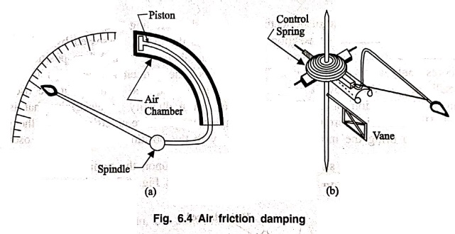
Two methods of air
friction damping are shown in Fig. 6.4. In Fig. 6.4 (a) the light aluminium
piston, attached to the moving system travel with a very small clearance, fixed
air chamber closed at one end. The cross‒section of the chamber is either
circular or rectangular. Damping of the oscillations is affected by the
compression and suction actions of the piston on the air‒enclosed in the
chamber. Such a system of damping is not much favourable these days, than those
shown ion Fig. 6.4 (b). In the latter method, one or two light aluminium vanes
are mounted on the spindle of the moving system, which moves in a closed sector‒shaped
box.
2. Fluid Friction Damping
In this method the
friction drag exerted on the movement of a disc inside the pot fluid is
utilised. In this type of damping careful fitting is required, in the previous
method it is not necessary. A light vane or disc attached to the spindle of the
moving system, dips into a pot of a viscous liquid and it should be completely
submerged by the oil. The Fig. 6.5 illustrates the method. There is no
frictional force when the disc is stationary and a frictional drag acts on the
disc when it moves and the amount of force acting is proportional to be speed
of motion. The suspending system of the disc should be cylindrical and of least
diameter where it penetrates the oil surface. So as to minimise effects due to
surface tension.
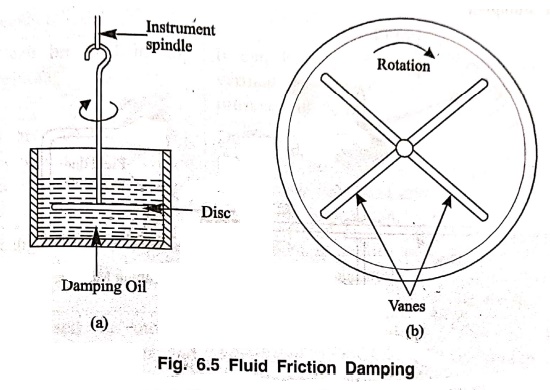
In second system
instead of a disc a pair of vanes rigidly fixed at right angles is made to
rotate into a cylindrical pot of oil. An increased damping when compared to the
previous system is obtained by using vanes.
Principle
The principle
requirements of the oil used for damping are:
(i) It should not
evaporate quickly.
(ii). Do not have
corrosive action on metals.
(iii) Sufficient
viscous.
(iv) The viscosity
should not change appreciably with temperature,
(v) Should be a good
insulator.
Advantages
(a) Due to more
viscosity of fluid, more damping is provided.
(b) The oil can also be
used for insulation purposes,
(e) Due to up thrust of
oil, the load on the bearing is reduced thus frictional errors, are reduced.
Disadvantages
(a) This can be
applicable only for instruments which are vertical in position.
(b) Due to oil leakage,
the instruments cannot be kept clean.
3. Eddy Current Damping
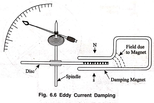
On the above types of
damping the most efficient form of damping is the eddy current damping. The
damping utilised is a critical damping of its nature and hence such instruments
using eddy current damping are called "Dead Beat" instruments.
In this method, a thin
disc of a conducting non magnetic material like copper or aluminium mounted on
the spindle which carriers the moving system and the pointer of the instrument.
The disc so positioned that its edge, when in rotation, cuts the magnetic flux
between the poles of a permanent magnet. Hence eddy currents are produced in
the disc which flow and so produce a damping force in such a direction so as to
oppose the cause producing them (Lenz's law). Since the cause producing them is
the rotation of the disc, these eddy currents retard the motion of the disc and
the moving system as a whole. Comparison between the types are given below:
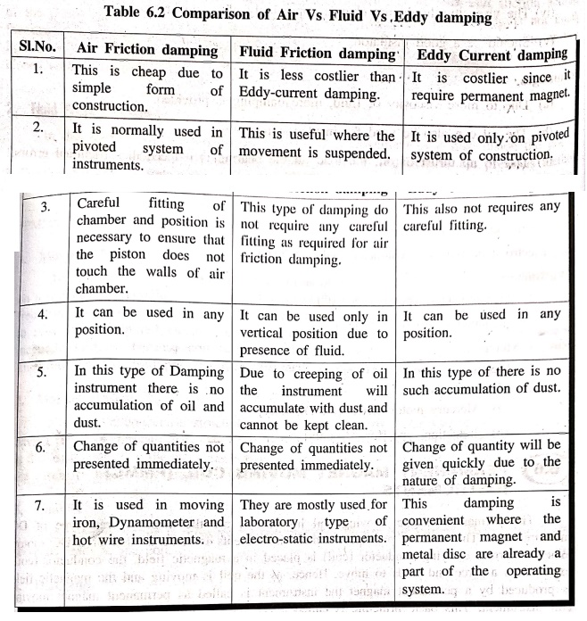
Table
6.2 Comparison of Air Vs Fluid Vs Eddy damping
Basic Electronics and Electrical Engineering: Chapter 6: Measurement and Instrumentation : Tag: Basic Engineering : - Essential Torques of Indicating Instruments
Basic Electronics and Electrical Engineering: Chapter 6: Measurement and Instrumentation
Under Subject

Basic Electronics and Electrical Engineering
EE25C04 1st Semester ECE Dept | 2025 Regulation | 2nd Semester 2025 Regulation
Related Subjects

English Essentials I
EN25C01 1st Semester | 2025 Regulation | 1st Semester 2025 Regulation

தமிழர் மரபு - Heritage of Tamils
UC25H01 1st Semester | 2025 Regulation | 1st Semester 2025 Regulation

Applied Calculus
MA25C01 Maths 1 M1 - 1st Semester | 2025 Regulation | 1st Semester 2025 Regulation

Applied Physics I
PH25C01 1st Semester | 2025 Regulation | 1st Semester 2025 Regulation

Applied Chemistry I
CY25C01 1st Semester | 2025 Regulation | 1st Semester 2025 Regulation

Makerspace
ME25C04 1st Semester | 2025 Regulation | 1st Semester 2025 Regulation

Computer Programming C
CS25C01 1st Semester | 2025 Regulation | 1st Semester 2025 Regulation

Computer Programming Python
CS25C02 1st Semester | 2025 Regulation | 1st Semester 2025 Regulation

Fundamentals of Electrical and Electronics Engineering
EE25C03 1st Semester | 2025 Regulation | 1st Semester 2025 Regulation

Introduction to Mechanical Engineering
ME25C03 1st Semester | 2025 Regulation | 1st Semester 2025 Regulation

Introduction to Civil Engineering
CE25C01 1st Semester Civil Department | 2025 Regulation | 1st Semester 2025 Regulation

Essentials of Computing
CS25C03 1st Semester - AID CSE IT Department | 2025 Regulation | 1st Semester 2025 Regulation

Applied Physics I Laboratory
PH25C01 1st Semester practical Laboratory Manual | 2025 Regulation | 1st Semester Laboratory 2025 Regulation

Applied Chemistry I Laboratory
CY25C01 1st Semester practical Laboratory Manual | 2025 Regulation | 1st Semester Laboratory 2025 Regulation

Computer Programming C Laboratory
CS25C01 1st Semester practical Laboratory Manual | 2025 Regulation | 1st Semester Laboratory 2025 Regulation

Computer Programming Python Laboratory
CS25C02 1st Semester practical Laboratory Manual | 2025 Regulation | 1st Semester Laboratory 2025 Regulation

Engineering Drawing
ME25C01 EEE Mech Dept | 2025 Regulation | 2nd Semester 2025 Regulation
Basic Electronics and Electrical Engineering
EE25C04 1st Semester ECE Dept | 2025 Regulation | 2nd Semester 2025 Regulation