Basic Electronics and Electrical Engineering: Chapter 6: Measurement and Instrumentation
Energy Meter (Measurement of Energy)
Construction, Working Principle, Theory, Advantages, Limitations
Energy is a measure of power over a period of time or energy is the time integral of power.
MEASUREMENT OF ENERGY
Energy is a measure of
power over a period of time or energy is the time integral of power.
Energy = power × time.
If the time interval (t2‒
t1) is measured in seconds and the voltage 'e' in volts, current 'i'
in ampheres the energy, E is given by,
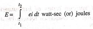
If the unit of time is
in hour and power is in watts, the energy unit will be in watt‒hour. Generally
unit of energy is given by kilowatt‒hour (KWhr). An energy meter will record
the energy consumed. Energy meters are indicating type of instruments.
Energy Meter
Construction
This is essentially a
split phase induction motor whose output is largely absorbed by its braking
system and dissipated as heat. It utilises two magnetic fields displaced in
space and time. There are four main parts of operating mechanism in an energy
meter. They are:
1. Driving system
2. Moving system
3. Braking system and
4. Registering
(counting) system
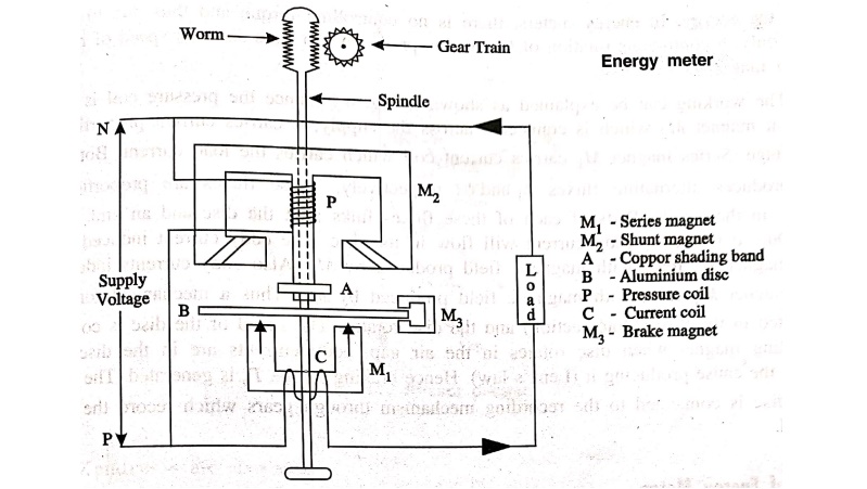
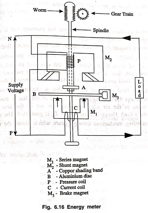
The pole arrangements
and connections of an induction type watt‒hour meter is shown in Fig. 6.16.
1.
Driving system
The driving system of
the meter consists of two electromagnets namely series and shunt. One is
excited by the load current and the other is by a current proportional to the
voltage of the circuit in which the energy is to measured. The coil wounded on
the current poles (series magnet) is known as "current coil" and that
on voltage pole (shunt magnet) is known as "pressure coil". The
pressure coil has a larger number of turns of thin wires, unlike the current
coil which has a few number of turns of thick wires.
Copper shading band is
provided on the central limb of shunt magnet and the position of the band is
adjustable. The function of the band is to bring the flux produced by the shunt
magnet exactly in quadrature with the applied voltage. The two copper bands
which are in the outer limbs of the shunt magnet is for friction compensation.
2.
Moving system
It consists of a thin
aluminium disc mounted on a light alloy shaft so that it is cut by the flux,
both the magnets. A pinion cut on the shaft at the top meshes with a gear wheel
on the revolution counter or register.
3.
Braking system
As permanent magnet
positioned near the edge of the aluminium disc as shown in Fig. 6.16, forms the
braking system. In the field on this magnet, the disc moves and hence provides
a braking torque. The position of the permanent magnet is radially adjustable
and hence the braking torque can be adjusted.
4.
Registering system
This system contains a
train of reduction gears, a pinion on the shaft which drives a series of
pointers. These pointers rotate on round dials which are equally marked with
equal divisions. This system records continuously a number which is
proportional to the revolutions made by the aluminium disc.
Working
It is working on the
principle of induction i.e., on the production of eddy currents in the moving
system by the alternating fluxes. These eddy current is induced in the moving
system interact with each other to produce a driving torque due to which disc
rotates to record the energy. In energy meters, there is no controlling torque
and thus due to driving torque only, a continuous rotation of the disc is
produced. To have constant speed of rotation, braking magnet is provided.
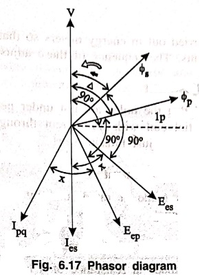
The working can be
explained as shown in fig. 6.17 since the pressure coil is carried by shunt
magnet M2 which is connected across the supply, it carries current
proportional to the voltage. Series magnet M1 carries current coil
which carries the load current. Both these coils produces alternating fluxes ϕ1
and ϕ2 respectively. These fluxes are proportional to currents in
their coils. Parts of each of these fluxes links with the disc and an emf
induces in it. Due to this emf, eddy current will flow in the disc. The eddy
current induced by the electromagnet M2 react with magnetic field
produced by M1. Also eddy currents induced by electromagnet M1
react with magnetic field produced by M2. Thus a mechanical force
will be exerted in the disc (Motor action) and the disc rotates. The speed of
the disc is controlled by braking magnet when disc rotates in the air gap, eddy
currents are in the disc which opposes the cause producing it (Lenz's law).
Hence braking torque Tb is generated. The spindle of the disc is
connected to the recording mechanism through gears which record the energy
supplied.
Theory of Energy Meter
Let,
V = Applied voltage.
IS = I = Load
current
Ip = Pressure
coil current
Eep = Eddy
emf induced due to ϕp
Ees = Eddy
emf induced due to ϕs
Ies = Eddy
current due to ϕs
Z = Impedance of eddy
current.
f
= frequency.
ϕ = Phase angle between
V and I
N = Speed or revolution
of disc.
Td ∝ ϕpϕs (f/Z) sinβ cos∝ ..... (1)
where,
β = (∆‒ϕ)
Td = K1ϕpϕs
(f/Z) sin(∆‒ϕ) cos∝
=
K2ϕpϕs sin(∆‒ϕ)
where,
f, Z and ∝ are constants.
We know that,
ϕp ∝ V
ϕs ∝ I
Td=K4VI
sin (∆‒ϕ) ..... (2)
The braking torque is
proportional to speed of disc (N)
Td ∝ N ..... (3)
Td = K3N ..... (4)
At steady speed, Td=Tb
K3N=K4
VI sin (∆‒ϕ)
N=KVI sin(∆‒ϕ)
where,
K= K4 / K3
if, ∆=90
N = KVI sin (90 ‒ ϕ)
N = KVI cos ϕ
N ∝ VI cos ϕ ..... (5)
Adjustments in Energy Meter
Some adjustments are
carried out in energy meters so that they read correctly and their errors are
within allowable limits. The sequence of these adjustments are;
1.
Preliminary light load adjustment
The disc is so
positioned that the holes are not under neath the electromagnets. Rated voltage
is applied to the potential coil with no current through the current coil. The
light load device is adjusted until the disc just fails to start.
2.
Full load unity power factor adjustment
The full load
adjustment is made at rated load by changing the radial position or effective
strength of the brake magnet.
3.
Lag adjustment (Low power factor adjustments
The lag adjustment,
usually made at resistance of a lag coil or by moving lag plate in radial
direction.
4. With rated supply
voltage, rated full load current and unity power factor, low power factor
adjustments are repeated until the desired accuracy limits are reached for both
conditions.
5.
Light bad adjustment
The light load
adjustment is made at 10% of rated load by moving a light load plate in a
direction parallel to the direction of motion of the meter.
6. The performance is
re‒checked at 0.5 power factor lagging.
7.
Creep adjustment
As a final check on
light load adjustment, the pressure coil is excited by 110% of rated voltage
with zero load current. If the light load adjustment is correct the meter should
not creep under these conditions.
Advantages
(i) Its construction is
simple and strong.
(ii) It is cheap in
cost.
(iii) Frictional errors
are less and hence accurate.
(iv) Less maintenance
is required.
Limitations
(i) Can be used only
for ac circuits.
(ii) Creeping can cause
errors.
Basic Electronics and Electrical Engineering: Chapter 6: Measurement and Instrumentation : Tag: Basic Engineering : Construction, Working Principle, Theory, Advantages, Limitations - Energy Meter (Measurement of Energy)
Basic Electronics and Electrical Engineering: Chapter 6: Measurement and Instrumentation
Under Subject

Basic Electronics and Electrical Engineering
EE25C04 1st Semester ECE Dept | 2025 Regulation | 2nd Semester 2025 Regulation
Related Subjects

English Essentials I
EN25C01 1st Semester | 2025 Regulation | 1st Semester 2025 Regulation

தமிழர் மரபு - Heritage of Tamils
UC25H01 1st Semester | 2025 Regulation | 1st Semester 2025 Regulation

Applied Calculus
MA25C01 Maths 1 M1 - 1st Semester | 2025 Regulation | 1st Semester 2025 Regulation

Applied Physics I
PH25C01 1st Semester | 2025 Regulation | 1st Semester 2025 Regulation

Applied Chemistry I
CY25C01 1st Semester | 2025 Regulation | 1st Semester 2025 Regulation

Makerspace
ME25C04 1st Semester | 2025 Regulation | 1st Semester 2025 Regulation

Computer Programming C
CS25C01 1st Semester | 2025 Regulation | 1st Semester 2025 Regulation

Computer Programming Python
CS25C02 1st Semester | 2025 Regulation | 1st Semester 2025 Regulation

Fundamentals of Electrical and Electronics Engineering
EE25C03 1st Semester | 2025 Regulation | 1st Semester 2025 Regulation

Introduction to Mechanical Engineering
ME25C03 1st Semester | 2025 Regulation | 1st Semester 2025 Regulation

Introduction to Civil Engineering
CE25C01 1st Semester Civil Department | 2025 Regulation | 1st Semester 2025 Regulation

Essentials of Computing
CS25C03 1st Semester - AID CSE IT Department | 2025 Regulation | 1st Semester 2025 Regulation

Applied Physics I Laboratory
PH25C01 1st Semester practical Laboratory Manual | 2025 Regulation | 1st Semester Laboratory 2025 Regulation

Applied Chemistry I Laboratory
CY25C01 1st Semester practical Laboratory Manual | 2025 Regulation | 1st Semester Laboratory 2025 Regulation

Computer Programming C Laboratory
CS25C01 1st Semester practical Laboratory Manual | 2025 Regulation | 1st Semester Laboratory 2025 Regulation

Computer Programming Python Laboratory
CS25C02 1st Semester practical Laboratory Manual | 2025 Regulation | 1st Semester Laboratory 2025 Regulation

Engineering Drawing
ME25C01 EEE Mech Dept | 2025 Regulation | 2nd Semester 2025 Regulation
Basic Electronics and Electrical Engineering
EE25C04 1st Semester ECE Dept | 2025 Regulation | 2nd Semester 2025 Regulation