Basic Electronics and Electrical Engineering: Chapter 6: Measurement and Instrumentation
Pivoted Coil, Direct Indicating Electro Dynamometer Type Wattmeter
Construction, Operation, Theory, Errors, Advantages and Limitations
1. Construction and Operation 2. Theory of Electrodynamometer Type Wattmeter 3. Errors in dynamometer type wattmeters 4. Advantages and Limitations
PIVOTED
COIL, DIRECT INDICATING ELECTRO DYNAMOMETER TYPE WATTMETER
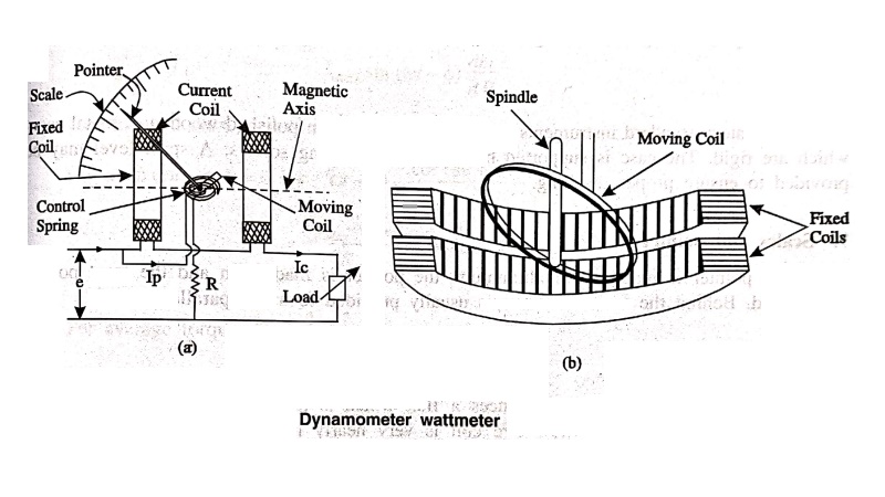
Construction and Operation
The constructional
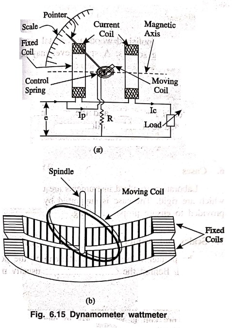
details of pivoted coil direct indicated electro dynamometer is shown in Fig.
6.15. These instruments are similar in design and construction to a dynamometer
type voltmeter or Ammeter. The two coils namely, fixed coils and moving coils
are connected in different ways for the measurement of power.
1.
Fixed coil and moving coil
The fixed c coils are
connected in series with the load so as to carry the rated load current and is
called as “current coil" of the wattmeter. The moving coil is connected
across the voltage and therefore, carries a current proportional to the
voltage. A high non‒inductive resistor is added
in series with the
moving coil to limit the current to a small value and this coil is called as
"pressure coil" or "voltage coil" of the wattmeter.
2.
Moving system
The moving coil is
mounted on a spindle which rests in the jewelled bearing. A pointer and the
damping vane are attached to the spindle. Balancing weight is also attached to
the moving system and is adjusted such that the centre of gravity lies in the
centre of the spindle.
3.
Control
The moving system of
the dynamometer type wattmeters are usually spring controlled. This makes the
instruments to a portable one.
4.
Damping
Air friction damping is
used. The moving system carries a light aluminium vane which moves in a sector
shaped box or a piston which moves in an aluminium cylinder.
5.
Shielding
The field produced by
these instruments is very weak. Even earth's magnetic field considerably
affects the reading. So shielding is done to protect it from stray magnetic
fields. It is done by enclosing in a casing of high permeability alloy.
6.
Cases
Laboratory standard
instruments are usually contained in polished wooden or metal cases which are
rigid. The case is supported by adjustable levelling screws. A spirit level may
be provided to ensure proper levelling.
7.
Scales and pointer
The pointer is made up
of aluminium, the pointer is made thin and the front portion is flattened.
Behind the scale, a mirror is usually provided to avoid parallax error.
Principle of operation
The pressure coil
produces a flux which is proportional to the applied voltage. The flux produced
by the pressure coil is very nearly in phase with the applied voltage. The
current coil produces a flux which is in phase with the load current. These two
fluxes link each other and a torque is produced on the moving system.
Theory of Electrodynamometer Type Wattmeter
Let,
i1 = instantaneous
current in pressure coil.
I2 = instantaneous
current in current coil.
θ = Angle by which the
applied voltage lags the current, through the current coil.
T1 = Instantaneous
torque.
Tav = Average
torque
Tc = Controlling torque
Vp = Voltage across the
pressure coil.
Rp = Resistance of the
pressure coil.
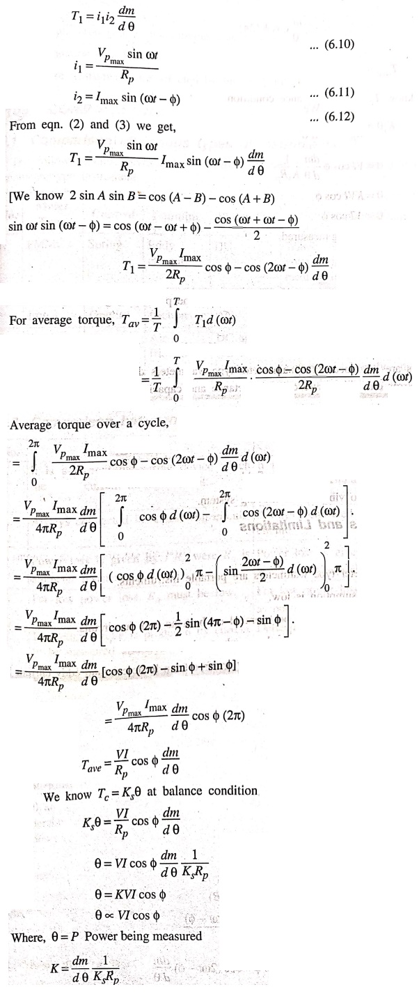
Since the deflection is
directly proportional to the power being measured and the scale is uniform over
a wide range.
Errors in dynamometer type wattmeters
Errors are introduced
in dynamometer type wattmeters due to the following errors:
1. Error due to
pressure coil's inductance and capacitance
2. Error due to mutual
inductance
3. Error due to
connection of wattmeter
4. Error due to eddy
currents
5. Error due to stray
magnetic field
6. Error due to
vibration of moving system.
Advantages and Limitations
Advantages
(i) Dynamometer type
wattmeters are portable instruments.
(ii) Power consumption
is low.
(iii) These instruments
can be operated on both ac and dc circuits.
(iv) By careful design
we can have sub‒standary accuracy.
(v) Since no iron parts
are used, they are free from hysteresis and eddy current losses.
Limitations
(i) Torque produced on
the moving system is low.
(ii) Production cost is
high.
(iii) These instruments
are affected by the stray magnetic fields.
Basic Electronics and Electrical Engineering: Chapter 6: Measurement and Instrumentation : Tag: Basic Engineering : Construction, Operation, Theory, Errors, Advantages and Limitations - Pivoted Coil, Direct Indicating Electro Dynamometer Type Wattmeter
Basic Electronics and Electrical Engineering: Chapter 6: Measurement and Instrumentation
Under Subject

Basic Electronics and Electrical Engineering
EE25C04 1st Semester ECE Dept | 2025 Regulation | 2nd Semester 2025 Regulation
Related Subjects

English Essentials I
EN25C01 1st Semester | 2025 Regulation | 1st Semester 2025 Regulation

தமிழர் மரபு - Heritage of Tamils
UC25H01 1st Semester | 2025 Regulation | 1st Semester 2025 Regulation
Applied Calculus
MA25C01 Maths 1 M1 - 1st Semester | 2025 Regulation | 1st Semester 2025 Regulation
Applied Physics I
PH25C01 1st Semester | 2025 Regulation | 1st Semester 2025 Regulation

Applied Chemistry I
CY25C01 1st Semester | 2025 Regulation | 1st Semester 2025 Regulation
Makerspace
ME25C04 1st Semester | 2025 Regulation | 1st Semester 2025 Regulation
Computer Programming C
CS25C01 1st Semester | 2025 Regulation | 1st Semester 2025 Regulation
Computer Programming Python
CS25C02 1st Semester | 2025 Regulation | 1st Semester 2025 Regulation
Fundamentals of Electrical and Electronics Engineering
EE25C03 1st Semester | 2025 Regulation | 1st Semester 2025 Regulation
Introduction to Mechanical Engineering
ME25C03 1st Semester | 2025 Regulation | 1st Semester 2025 Regulation

Introduction to Civil Engineering
CE25C01 1st Semester Civil Department | 2025 Regulation | 1st Semester 2025 Regulation
Essentials of Computing
CS25C03 1st Semester - AID CSE IT Department | 2025 Regulation | 1st Semester 2025 Regulation

Applied Physics I Laboratory
PH25C01 1st Semester practical Laboratory Manual | 2025 Regulation | 1st Semester Laboratory 2025 Regulation

Applied Chemistry I Laboratory
CY25C01 1st Semester practical Laboratory Manual | 2025 Regulation | 1st Semester Laboratory 2025 Regulation

Computer Programming C Laboratory
CS25C01 1st Semester practical Laboratory Manual | 2025 Regulation | 1st Semester Laboratory 2025 Regulation

Computer Programming Python Laboratory
CS25C02 1st Semester practical Laboratory Manual | 2025 Regulation | 1st Semester Laboratory 2025 Regulation
Engineering Drawing
ME25C01 EEE Mech Dept | 2025 Regulation | 2nd Semester 2025 Regulation
Basic Electronics and Electrical Engineering
EE25C04 1st Semester ECE Dept | 2025 Regulation | 2nd Semester 2025 Regulation