Basic Electronics and Electrical Engineering: Chapter 2: DC Machines
Characteristics of DC Generators
The following are the three most important characteristics of a DC generator. 1. Characteristics of Separately ‒ Excited Generator 2. Characteristics of DC Shunt Generator
CHARACTERISTICS
OF DC GENERATORS
The following are the
three most important characteristics of a DC generator.
1. Open Circuit Characteristic (OCC) (or) Magnetisation characteristic (or) No load characteristic (E0/If).
It shows the relation
between the no load generated emf in armature, E0 and field or
exciting current If at a
given fixed speed. Its shape is practically the same for all generators whether
separately or self excited.
2. Internal or Total characteristic (E/Ia)
It gives the relation
between the generated emf on load (E) and the armature current (Ia).
The emf E is less than E0 due to demagnetising effect of armature
reaction. Therefore, this curve will lie below the open circuit characteristic
(OCC). The internal characteristic is of interest chiefly to the designer. It
cannot be obtained directly by experiment. It is because a voltmeter cannot
read the emf generated on load due to the voltage drop in armature resistance.
The internal characteristic can be obtained from external characteristic if
winding resistance are known because armature reaction effect is included in
both characteristics.
3. External Characteristic (V/IL)
It gives the relation
between the terminal voltage (V) and load current (IL). The terminal
voltage V will be less than E due to voltage drop in the armature circuit.
Therefore this curve will lie below the internal characteristic. This characteristic
is very important in determining the suitability of a generator for a given
purpose. It can be obtained by making simultaneous measurements of terminal
voltage and load current (with voltmeter and ammeter) of a loaded generator.
Characteristics of Separately ‒ Excited Generator
1. Open Circuit Characteristics (OCC) (or) Magnetisation characteristics (or) No Load characteristics. (E0/Iƒ)
The arrangement for
obtaining the necessary data to plot this curve is shown in Fig. 2.18 (a).
It shows the variation
of no load generated emf (E0) with the field current (If) at constant speed.
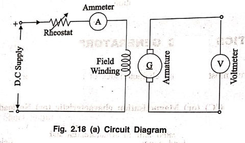
The armature is driven
at a constant speed by a prime mover with no load. The field winding is excited
from a separate DC source to ensure independent flux control.
The voltage equation of
a d.c. generator is,
Eg = (ϕΖΝ / 60) × (P/A) Volt
Since speed is
constant, the above relation becomes Eg ∝ ϕ
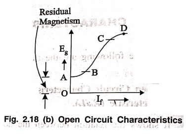
When the field current
is zero, a small residual flux is present in the magnetic poles and therefore a
small voltage is generated (residual emf) even when field current is zero,
which is appearing across the armature can be taken as no load voltage. (OA ‒
Residual emf)
The field current is
increased in steps using rheostat, the flux increases proportionately and no
load voltage increase with If
till the poles are unsaturated.
On plotting the
relation between E0 and If,
we get the open circuit characteristics as shown in Fig. 2.18 (b).
We can observe that the
major portion of this characteristics (B‒C) is linear. There are two non linear
portions A ‒ B and C ‒ D. Beyond the operating point D, we can say that the
poles are saturated and so there will not be any appreciable increase in the
generated voltage even for large increase in field current.
The build
up of voltage of DC shunt generator under open circuited condition depends on
the following factors.
(i) Residual flux
(ii) Reverse connection
of shunt field
(iii) Shunt field
circuit resistance and
(iv) Speed of armature.
• If there is no
residual flux, no emf is induced. As a result there is no further induced emf.
As a result there is no further increase in field flux and the induced emf is
zero.
• The residual flux and
the flux produced by the shunt field winding must aid each other. So that the
net air gap flux increases which in turn develops voltage other wise, the residual
flux may get wiped off and hence induced emf drops to zero. So the field
winding terminals should be properly connected.
• The field circuit
resistance must be equal to or less than the critical field resistance RC,
otherwise the generator will fail to build up voltage.
• The speed of
generator must be equal to or greater than the critical speed Nc of
the generator, otherwise, the generator will fail to build up voltage.
2. Internal and External characteristics
The external
characteristics is the graph of the terminal voltage V, against load current ĮL.
The internal
characteristics is the graph of the generated induced emf, E against the
armature current, la.
While plotting both the
characteristics, the speed of the generator is maintained constant.
These characteristics
is also known as load characteristics of
generator.
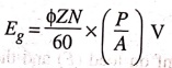
To plot the load
characteristics the circuit arrangement is shown in Fig. 2.19.
The generator is made
to run at its rated speed by prime mover. Field current is adjusted using
rheostat to generate the rated voltage at no load. If there were no armature
reaction and armature voltage drop, then this voltage would have remain
constant as shown in Fig. 2.20 by the horizontal line I.
Now by varying the load
the terminal voltage V and load current IL are noted from voltmeter
and ammeter respectively. The readings are plotted as shown in Fig. 2.20. The
terminal voltage of the generator decreases on loading. This is because of,
(i) Voltage drop due to
armature reaction,
(ii) Voltage drop due
to armature resistance, Ra
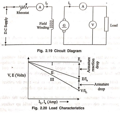
If we subtract from E0
the values of voltage drops due to armature reaction for different loads, then
we get the value of E ‒ the emf actually induced in the armature under load
conditions. Curve II is plotted in this way and is known as the internal
characteristics [∴
E/Ia]. These two quantities are internal quantities for the
generator and E cannot be measured directly, but it can be estimated. Hence the
name Internal characteristics.
If we subtract from E
the armature drop, IaRa we get terminal voltage, V Curve
III represent the external characteristics [i.e., V/IL]. These quantities
two are external quantities and they can be measured directly. Hence the name
external characteristics.
(i)
Critical Field Resistance (Rc)
It is the maximum value
of resistance in the field circuit with which the generator will just build up
voltage. Beyond this value of resistance the machine will fail to build up
voltage.
(ii)
Critical Speed (Nc)
It is the minimum speed
at which the generator will just build up voltage. Below this critical speed it
will fail to build up voltage.
The critical speed (Nc)
and the critical field resistance Rc of generator can be obtained from its OCC
at rated speed as discussed as follows.

Draw the OCC at rated
speed (NR). Draw the tangent to the initial portion of the OCC. The
slope of the tangent gives,
Rc = AC/OC
Now, measure the value
Rsh of the generator and draw the line representing field circuit
resistance. Draw any ordinate which cuts the Rc line, Rsh line and X
axis at A, B and C.
The critical speed is
calculated as
Nc = (BC/AC) × Rated
speed (NR)
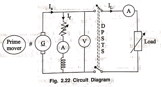
Characteristics of DC Shunt Generator
To plot the
characteristics of DC shunt generator the circuit diagram is shown in Fig.
2.22.
1. OCC
The armature is driven
at rated speed by a prime mover, with no load. The field current is increased
in steps using rheostat, and the Voltmeter reading E0 and Ammeter
reading If are noted. From
the reading OCC are drawn as shown in Fig. 2.23.

2. Load characteristics
The connection diagram
for conducting the load test is shown in Fig. 2.22.
The generator is made
to run at its rated speed by prime mover. Field current is adjusted using
rheostat to generate rated voltage at no load. The load is increased step by
step up to rated current of the generator, while increasing the load the
voltmeter reading (V) and ammeter reading (IL) are noted and these
reading are plotted as shown in Fig. 2.24.
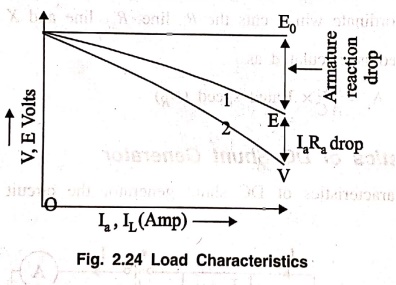
Curve
(1) Shows the Internal Characteristics (EVSIa)
When the generator is
loaded, the flux per pole is reduced due to armature reaction, Therefore emf
generated on load is less than the emf generated at no load. So internal
characteristics lies below the open circuit voltage curve.
Curve
(2) Shows the External characteristic of a shunt generator
It gives the relation
between terminal voltage V and load current IL.
V = E‒laRa = E ‒ (IL+Ish)Ra
Therefore External
characteristic curve will lie below the internal characteristic curve by an
amount equal to drop in the armature circuit [i.e., (IL+Ish)Ra]
as shown in Fig. 2.24.
Basic Electronics and Electrical Engineering: Chapter 2: DC Machines : Tag: Basic Engineering : - Characteristics of DC Generators
Basic Electronics and Electrical Engineering: Chapter 2: DC Machines
Under Subject

Basic Electronics and Electrical Engineering
EE25C04 1st Semester ECE Dept | 2025 Regulation | 2nd Semester 2025 Regulation
Related Subjects

English Essentials I
EN25C01 1st Semester | 2025 Regulation | 1st Semester 2025 Regulation

தமிழர் மரபு - Heritage of Tamils
UC25H01 1st Semester | 2025 Regulation | 1st Semester 2025 Regulation

Applied Calculus
MA25C01 Maths 1 M1 - 1st Semester | 2025 Regulation | 1st Semester 2025 Regulation

Applied Physics I
PH25C01 1st Semester | 2025 Regulation | 1st Semester 2025 Regulation

Applied Chemistry I
CY25C01 1st Semester | 2025 Regulation | 1st Semester 2025 Regulation

Makerspace
ME25C04 1st Semester | 2025 Regulation | 1st Semester 2025 Regulation

Computer Programming C
CS25C01 1st Semester | 2025 Regulation | 1st Semester 2025 Regulation

Computer Programming Python
CS25C02 1st Semester | 2025 Regulation | 1st Semester 2025 Regulation

Fundamentals of Electrical and Electronics Engineering
EE25C03 1st Semester | 2025 Regulation | 1st Semester 2025 Regulation

Introduction to Mechanical Engineering
ME25C03 1st Semester | 2025 Regulation | 1st Semester 2025 Regulation

Introduction to Civil Engineering
CE25C01 1st Semester Civil Department | 2025 Regulation | 1st Semester 2025 Regulation

Essentials of Computing
CS25C03 1st Semester - AID CSE IT Department | 2025 Regulation | 1st Semester 2025 Regulation

Applied Physics I Laboratory
PH25C01 1st Semester practical Laboratory Manual | 2025 Regulation | 1st Semester Laboratory 2025 Regulation

Applied Chemistry I Laboratory
CY25C01 1st Semester practical Laboratory Manual | 2025 Regulation | 1st Semester Laboratory 2025 Regulation

Computer Programming C Laboratory
CS25C01 1st Semester practical Laboratory Manual | 2025 Regulation | 1st Semester Laboratory 2025 Regulation

Computer Programming Python Laboratory
CS25C02 1st Semester practical Laboratory Manual | 2025 Regulation | 1st Semester Laboratory 2025 Regulation

Engineering Drawing
ME25C01 EEE Mech Dept | 2025 Regulation | 2nd Semester 2025 Regulation
Basic Electronics and Electrical Engineering
EE25C04 1st Semester ECE Dept | 2025 Regulation | 2nd Semester 2025 Regulation