Basic Electronics and Electrical Engineering: Chapter 2: DC Machines
Types of DC Generator Armature Winding
There are two methods of placing the armature conductors in the slots namely: (i) Single layer winding (ii) Double layer winding
TYPES
OF ARMATURE WINDING
There are two methods
of placing the armature conductors in the slots namely:
(i) Single layer
winding
(ii) Double layer
winding
In single layer
winding, only one conductor or coil side is placed in each armature slot. Such
a winding is not much used.
In double layer
winding, there are two conductors or coil sides placed in each slot.
According to the way of
connecting the conductors, armature winding has basically two types namely:
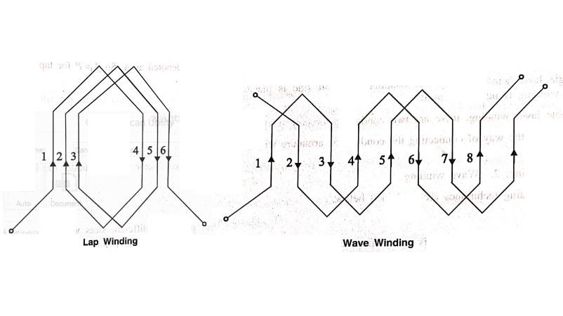
1. Lap winding,
2. Wave winding
Both the winding
techniques are explained below.
1. Lap Winding
In this case, if
connection is started from conductor in slot 1 then connections overlap each
other as winding proceeds till starting point is reached again.
Developed view part of
the armature winding in lap fashion is shown in the Fig. 2.5

As seen from the Fig.
2.5 there is overlapping of coils. While proceeding, due to such connection,
the total numbers of conductors get divided into P number of parallel paths,
where P= number of poles in the machine. Large number of parallel paths
indicate high current capacity of machine, hence lap winding is preferred for
high current rating generators.
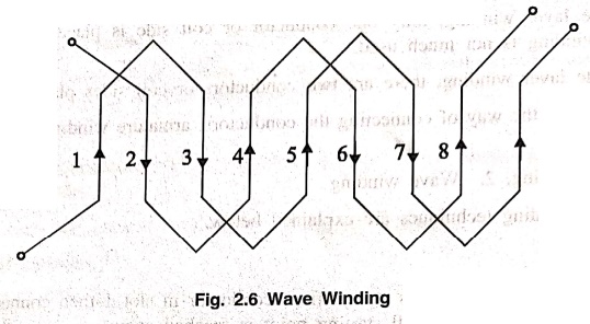
2. Wave Winding
In this type of
connection, winding always travels ahead avoiding overlapping. It travels like
a progressive wave hence called wave winding.
A part of armature
winding in wave fashion is shown in Fig. 2.6.
Both coils starting
from slot 1 and slot 2 are progressive in wave fashion.
Due to this type of
connection, the total number of conductor get divided into two number of
parallel paths always, irrespective of number of poles of the machine. As
number of parallel paths are less, it is preferable for low current, high
voltage capacity generators.
The number of parallel
paths in which armature conductors are divided due to lap or wave fashion of
connection is denoted as A. So A=P for lap connection and A=2 for wave connection.
Winding Terminologies
1.
Conductor
It is the actual
armature conductor which is under the influence of the magnetic field, placed
in the armature slot.
2.
Turn
The two conductors
placed in different slots when connected together, forms a turn, while
describing armature winding the number of turns may be specified from which,
the number of conductors can be decided.
Z=2×Number of turns.
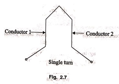
3.
Coil
For simplicity of
connections the turns are grouped together to form a coil. If coil contains
only one turn it is called single turn coil while coil contains more than one
turn is called multi turn coil.

4.
Commutator Pitch (Yc)
The commutator pitch is
the number of commutator segments spanned by each coil of the winding. It is
denoted by Yc.
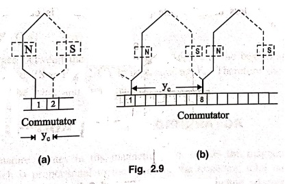
In Fig. 2.9 (a), one
side of the coil is connected to the commutator segment 1 and the other side
connected to commutator segment 2. Therefore the number of commutator segments
spanned by the coil is 1 i.e., Yc = 1.
In Fig. 2.9 (b), one
side of the coil is connected to commutator segment 1 and the other side to
commutator segment 8. Therefore, the number of commutator segments spanned by
the coil =8‒1=7 segments. i.e., Yc=7. The commutator pitch of winding is always
a whole number, since each coil has two ends and as two coil connections are
joined at each commutator segments,
Number of coils =
Number of commutator segments.
For example, if an
armature has 30 conductors, the number of coils will be 30/2 = 15. Therefore,
number of commutator segments is also an important factor in determining the
type of DC armature winding.
5.
Pole pitch
The distance between
the centers of two adjacent poles is called pole pitch. One pole pitch equals
to 180 electrical degrees. It is also defined as the number of slots per pole.
Thus if a 4‒pole
generator has 16 coils, then number of slots = 16
.. Pole pitch = 16/4= 4
slots.
6.
Coil span
The distance between
the two coil sides of a coil is called coil span. It is expressed in electrical
degrees or in number of slots.
7.
Full Pitched winding
If the coil span is
equal to pole pitch, the winding is called as full pitched winding.
8.
Short Pitched Winding
If the coil span is
less than the pole pitch, the winding is called as short pitched or short
chorded winding.
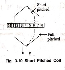
For example, the pole
pitch for a 4‒pole, 24 slot machine is 24/46 slots. If the coil sides of one
coil are placed in slots 1 and 7 as shown in Fig. 2.10, then it is full pitched
winding. If they are placed in 1 and 6, then it is short pitched winding.
(short chorded by one slot i.e., 180/6 = 30 electrical degrees).
9.
Back pitch (YB)
It is the distance
measured in terms of armature conductors between the two sides of coil at the
back of the armature (see Fig. 2.11). It is denoted by YB. For
example if a coil is formed by connecting conductor 1 (Upper conductor in a
slot) to conductor 12 (bottom conductor in another slot) at the back of the
armature, then back pitch is YB = 12−1 = 11 conductors.
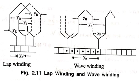
10.
Front Pitch (YF)
It is the distance
measured in terms of armature conductor between the coil sides attached to any
one commutator segment (see Fig. 2.11). It is denoted by YF. For
example, if coil side 12 and coil side 3 are connected to the same commutator
segment, then front Side pitch is YF = 12‒3 = 9 conductors.
11.
Resultant Pitch (YR)
It is the distance
between the beginning of one coil and the beginning of the next coil to which
it is connected. (See Fig. 2.11) It is dented by YR. Therefore the
resultant pitch is the algebraic sum of the back and front pitches.
Basic Electronics and Electrical Engineering: Chapter 2: DC Machines : Tag: Basic Engineering : - Types of DC Generator Armature Winding
Basic Electronics and Electrical Engineering: Chapter 2: DC Machines
Under Subject

Basic Electronics and Electrical Engineering
EE25C04 1st Semester ECE Dept | 2025 Regulation | 2nd Semester 2025 Regulation
Related Subjects

English Essentials I
EN25C01 1st Semester | 2025 Regulation | 1st Semester 2025 Regulation

தமிழர் மரபு - Heritage of Tamils
UC25H01 1st Semester | 2025 Regulation | 1st Semester 2025 Regulation

Applied Calculus
MA25C01 Maths 1 M1 - 1st Semester | 2025 Regulation | 1st Semester 2025 Regulation

Applied Physics I
PH25C01 1st Semester | 2025 Regulation | 1st Semester 2025 Regulation

Applied Chemistry I
CY25C01 1st Semester | 2025 Regulation | 1st Semester 2025 Regulation

Makerspace
ME25C04 1st Semester | 2025 Regulation | 1st Semester 2025 Regulation

Computer Programming C
CS25C01 1st Semester | 2025 Regulation | 1st Semester 2025 Regulation

Computer Programming Python
CS25C02 1st Semester | 2025 Regulation | 1st Semester 2025 Regulation

Fundamentals of Electrical and Electronics Engineering
EE25C03 1st Semester | 2025 Regulation | 1st Semester 2025 Regulation

Introduction to Mechanical Engineering
ME25C03 1st Semester | 2025 Regulation | 1st Semester 2025 Regulation

Introduction to Civil Engineering
CE25C01 1st Semester Civil Department | 2025 Regulation | 1st Semester 2025 Regulation

Essentials of Computing
CS25C03 1st Semester - AID CSE IT Department | 2025 Regulation | 1st Semester 2025 Regulation

Applied Physics I Laboratory
PH25C01 1st Semester practical Laboratory Manual | 2025 Regulation | 1st Semester Laboratory 2025 Regulation

Applied Chemistry I Laboratory
CY25C01 1st Semester practical Laboratory Manual | 2025 Regulation | 1st Semester Laboratory 2025 Regulation

Computer Programming C Laboratory
CS25C01 1st Semester practical Laboratory Manual | 2025 Regulation | 1st Semester Laboratory 2025 Regulation

Computer Programming Python Laboratory
CS25C02 1st Semester practical Laboratory Manual | 2025 Regulation | 1st Semester Laboratory 2025 Regulation

Engineering Drawing
ME25C01 EEE Mech Dept | 2025 Regulation | 2nd Semester 2025 Regulation
Basic Electronics and Electrical Engineering
EE25C04 1st Semester ECE Dept | 2025 Regulation | 2nd Semester 2025 Regulation