Basic Electronics and Electrical Engineering: Chapter 2: DC Machines
Principle of DC Generator
An electrical generator is a rotating machine, which converts mechanical energy into electrical energy. It operates on the principle based on Faraday's law of electromagnetic induction.
GENERATOR
PRINCIPLE
An electrical generator
is a rotating machine, which converts mechanical energy into electrical energy.
It operates on the principle based on Faraday's law of electromagnetic
induction.
According to Faraday's
Law of electromagnetic induction, when a conductor is rotated in a magnetic
field to cut the magnetic lines of flux, dynamically induced emf is produce in
the conductor. This emf causes a current to flow if the conductor circuit is
closed. The direction of the current is found by Fleming's Right Hand Rule.
Hence, the basic
requirements for the dynamically induced emf to exist are the following
(i) A steady magnetic
field.
(ii) A conductor or
coils.
(iii) Relative motion
between the magnetic field and the conductors.
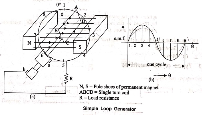
Simple Loop Generator

Consider a single‒turn
rectangular copper coil ABCD rotating clockwise in a magnetic field provided by
permanent magnet or electromagnets as shown in Fig. 2.2 (a). The two ends of
the coil are joined to two Slip‒rings 'a' and 'b' which are insulated from each
other and from the central shaft. Two collecting brushes (of carbon or copper)
press against the slip rings. Their function is to collect the current induced
in the coil and to convey it to the external load resistance.
The rotating coil may
be called 'armature' and the magnets as "field magnets". It is
rotated in clockwise direction at an uniform magnetic field.
At position 1 (θ=0°),
the plane of the coil is perpendicular to the direction of lines of flux. Now,
the flux linked with the coil is maximum. But the rate of change of flux
linkages is minimum. So, no emf is induced in 'the coil. That is at the
starting position emf induced is zero.
When the coil is
rotated further, the rate of change of flux linkage increases upto position, 3
(θ=90°). At this position, the plane of the coil is parallel to the lines of
flux. Now, the flux linked with the coil is minimum, but rate of change of flux
linkages is maximum. Therefore, at this position emf induced in the coil is
maximum.
On further rotation of
the coil from position 3(θ = 90°) to position 5 (θ = 180°) the rate of change
of flux linkages decreases, and the emf induced is gradually decreased.
At position 5 (θ =
180°), it is reduced to zero. The magnitude of emf with respect to the coil position
is indicated in Fig. 2.2 (b). From position 5 to position 7 (that is 180° to
270°), the induced emf value starts again from zero to maximum and from
position 7 to position 1 (from 270° to to 360°) maximum to zero in opposite
direction.
Note that emf generated
in the loop is alternating one. It is because any coil side, say AB has emf in
one direction when under the influence of N‒pole and CD in the other direction
when under the influence of S‒pole. If a load is connected across the ends of
the loop, then alternating current will flow through the load. The alternating
voltage generated in the loop can be converted into direct voltage by a device
called commutator.
Basic Electronics and Electrical Engineering: Chapter 2: DC Machines : Tag: Basic Engineering : - Principle of DC Generator
Basic Electronics and Electrical Engineering: Chapter 2: DC Machines
Under Subject

Basic Electronics and Electrical Engineering
EE25C04 1st Semester ECE Dept | 2025 Regulation | 2nd Semester 2025 Regulation
Related Subjects

English Essentials I
EN25C01 1st Semester | 2025 Regulation | 1st Semester 2025 Regulation

தமிழர் மரபு - Heritage of Tamils
UC25H01 1st Semester | 2025 Regulation | 1st Semester 2025 Regulation

Applied Calculus
MA25C01 Maths 1 M1 - 1st Semester | 2025 Regulation | 1st Semester 2025 Regulation

Applied Physics I
PH25C01 1st Semester | 2025 Regulation | 1st Semester 2025 Regulation

Applied Chemistry I
CY25C01 1st Semester | 2025 Regulation | 1st Semester 2025 Regulation

Makerspace
ME25C04 1st Semester | 2025 Regulation | 1st Semester 2025 Regulation

Computer Programming C
CS25C01 1st Semester | 2025 Regulation | 1st Semester 2025 Regulation

Computer Programming Python
CS25C02 1st Semester | 2025 Regulation | 1st Semester 2025 Regulation

Fundamentals of Electrical and Electronics Engineering
EE25C03 1st Semester | 2025 Regulation | 1st Semester 2025 Regulation

Introduction to Mechanical Engineering
ME25C03 1st Semester | 2025 Regulation | 1st Semester 2025 Regulation

Introduction to Civil Engineering
CE25C01 1st Semester Civil Department | 2025 Regulation | 1st Semester 2025 Regulation

Essentials of Computing
CS25C03 1st Semester - AID CSE IT Department | 2025 Regulation | 1st Semester 2025 Regulation

Applied Physics I Laboratory
PH25C01 1st Semester practical Laboratory Manual | 2025 Regulation | 1st Semester Laboratory 2025 Regulation

Applied Chemistry I Laboratory
CY25C01 1st Semester practical Laboratory Manual | 2025 Regulation | 1st Semester Laboratory 2025 Regulation

Computer Programming C Laboratory
CS25C01 1st Semester practical Laboratory Manual | 2025 Regulation | 1st Semester Laboratory 2025 Regulation

Computer Programming Python Laboratory
CS25C02 1st Semester practical Laboratory Manual | 2025 Regulation | 1st Semester Laboratory 2025 Regulation

Engineering Drawing
ME25C01 EEE Mech Dept | 2025 Regulation | 2nd Semester 2025 Regulation
Basic Electronics and Electrical Engineering
EE25C04 1st Semester ECE Dept | 2025 Regulation | 2nd Semester 2025 Regulation