Basic Electronics and Electrical Engineering: Chapter 5: Induction Motors
Construction of 3-phase Induction Motor
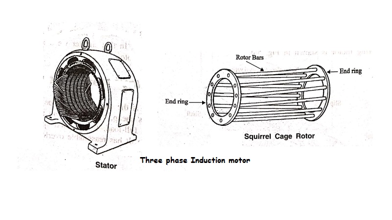
A 3‒phase induction motor consists of two main parts: 1. Stator 2. Rotor
CONSTRUCTION
OF 3‒PHASE INDUCTION MOTOR
A 3‒phase induction motor
consists of two main parts:
1. Stator
2. Rotor
Stator
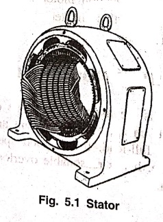
The stator is the
stationary part. It is built up of high‒grade alloy steel laminations to reduce
eddy‒current losses. The laminations are slotted on periphery and are insulated
and from each other. These laminations are supported in a stator frame of cast
iron or fabricated steel plates. The insulated conductors are placed in these
slots. These stator conductors are connected to form a three‒phase star or
delta connected winding and is fed from a 3‒phase supply. It is wound for a
definite number of poles, the exact number of poles being determined by the
requirement of speed. Greater the number of poles, lesser the speed and vice
versa. When 3‒phase supply is given to the stator winding, a rotating magnetic
field of constant magnitude is produced. This rotating magnetic field induces
current in the rotor by electro‒magnetic induction. [Ref Fig. 5.1]
Rotor
The rotor is also build
up of thin laminations of the same material as stator. The laminated core is
mounted directly on the shaft. These laminations are slotted on their outer
periphery to receive the rotor conductors. There are two different types of
induction motor rotors.
1. Squirrel cage rotor - Motors using this type of rotor are known as
squirrel cage induction motor.
2. Phase wound or wound rotor - Motors using this type of rotor are
known as slip ring motor (or) phase wound motor.
1. Squirrel Cage Rotor
The rotor consists of a
cylindrical laminated core with parallel slots or skewed type of slots. One
copper or aluminium bar is placed in each slot. At each end of the rotor, the
rotor bar conductors are short‒circuited by heavy end‒rings of the same
material, thus resemling a squirrel cage and hence the name. A squirrel cage
rotor is shown in Fig. 5.2.

The skewing of cage
rotor conductors offers the following advantages:
(i) More uniform torque
is produced and the noise is reduced during operation.
(ii) The locking
tendency of rotor is reduced. During locking, the rotor and stator teeth
attract each other due to magnetic action.
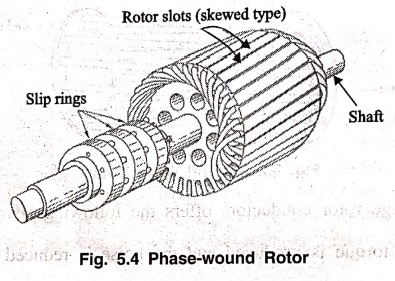
2. Phase‒wound rotor
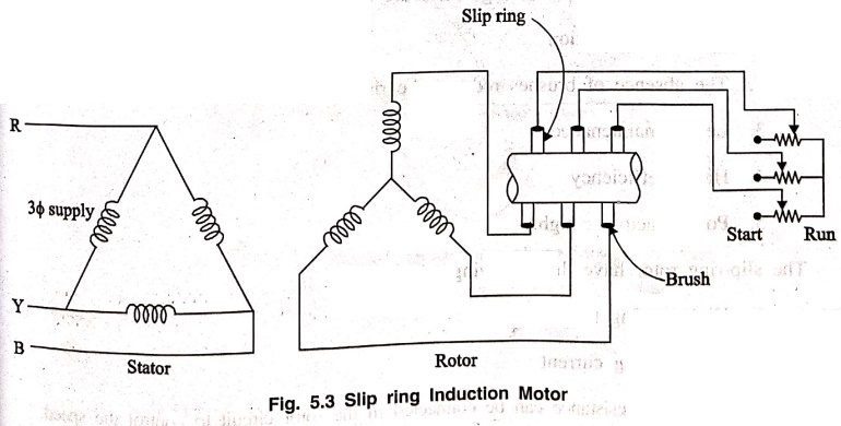
It consists of a
slotted armature Insulated conductors are put in the slots and connected to
form a three‒phase double layer distributed winding similar to the stator
winding. The rotor winding is uniformly distributed in the slots and is usually
star‒connected. The open ends of the stator circuit are brought out side the
rotor and connected to three insulated slip ring arrangement. The slip rings
are mounted on the shaft with brushes resting on them. The brushes are connected
to three variable resistors connected in star. At starting, the external
resistances are included in the rotor circuit to give a large starting torque.
These resistances are gradually reduced to zero as the motor runs up to rated
speed.
The external resistances
are used during starting period only. When the motor attains normal speed, the
three brushes are short‒circuited so that the wound rotor runs like a squirrel
cage rotor. A slip ring motor is shown in Fig. 5.4.
Basic Electronics and Electrical Engineering: Chapter 5: Induction Motors : Tag: Basic Engineering : - Construction of 3-phase Induction Motor
Basic Electronics and Electrical Engineering: Chapter 5: Induction Motors
Under Subject

Basic Electronics and Electrical Engineering
EE25C04 1st Semester ECE Dept | 2025 Regulation | 2nd Semester 2025 Regulation
Related Subjects

English Essentials I
EN25C01 1st Semester | 2025 Regulation | 1st Semester 2025 Regulation

தமிழர் மரபு - Heritage of Tamils
UC25H01 1st Semester | 2025 Regulation | 1st Semester 2025 Regulation

Applied Calculus
MA25C01 Maths 1 M1 - 1st Semester | 2025 Regulation | 1st Semester 2025 Regulation

Applied Physics I
PH25C01 1st Semester | 2025 Regulation | 1st Semester 2025 Regulation

Applied Chemistry I
CY25C01 1st Semester | 2025 Regulation | 1st Semester 2025 Regulation

Makerspace
ME25C04 1st Semester | 2025 Regulation | 1st Semester 2025 Regulation

Computer Programming C
CS25C01 1st Semester | 2025 Regulation | 1st Semester 2025 Regulation

Computer Programming Python
CS25C02 1st Semester | 2025 Regulation | 1st Semester 2025 Regulation

Fundamentals of Electrical and Electronics Engineering
EE25C03 1st Semester | 2025 Regulation | 1st Semester 2025 Regulation

Introduction to Mechanical Engineering
ME25C03 1st Semester | 2025 Regulation | 1st Semester 2025 Regulation

Introduction to Civil Engineering
CE25C01 1st Semester Civil Department | 2025 Regulation | 1st Semester 2025 Regulation

Essentials of Computing
CS25C03 1st Semester - AID CSE IT Department | 2025 Regulation | 1st Semester 2025 Regulation

Applied Physics I Laboratory
PH25C01 1st Semester practical Laboratory Manual | 2025 Regulation | 1st Semester Laboratory 2025 Regulation

Applied Chemistry I Laboratory
CY25C01 1st Semester practical Laboratory Manual | 2025 Regulation | 1st Semester Laboratory 2025 Regulation

Computer Programming C Laboratory
CS25C01 1st Semester practical Laboratory Manual | 2025 Regulation | 1st Semester Laboratory 2025 Regulation

Computer Programming Python Laboratory
CS25C02 1st Semester practical Laboratory Manual | 2025 Regulation | 1st Semester Laboratory 2025 Regulation

Engineering Drawing
ME25C01 EEE Mech Dept | 2025 Regulation | 2nd Semester 2025 Regulation
Basic Electronics and Electrical Engineering
EE25C04 1st Semester ECE Dept | 2025 Regulation | 2nd Semester 2025 Regulation