Basic Electronics and Electrical Engineering: Chapter 5: Induction Motors
Equivalent Circuit of Three Phase Induction Motor
Similar to a transformer, an induction motor can be represented by an equivalent electrical circuit.
EQUIVALENT CIRCUIT
Similar to a
transformer, an induction motor can be represented by an equivalent electrical
circuit. Equivalent circuit enables the performance characteristics of the
induction machine to be evaluated for steady state condition by ordinary
processes of AC network solution.
In the transformer the
load on the secondary is electrical, whereas in the induction motor, the load
is mechanical. However, in an equivalent circuit of the induction motor, the mechanical
load can be replaced by a pure resistance. The equivalent circuit of an
induction motor is drawn for only one phase.
As in the case of a
transformer, in this case also, the secondary values may be transferred to the
primary and vice versa.
Derivation of Equivalent circuit
1. Stator Side
In the stator side V1
= E1+I1(R1+jX1) where V is the
supply voltage and E1, is the emf induced in the stator winding as
shown in Fig. 5.14 (a).

We know that Iμ
lags behind V1 by 90° and so it is presumed to flow through an
assumed inductive reactance X0 ohms. Similarly the loss component of
the no‒load current, Iw is assumed to flow through a fictitious
resistance R0.
Hence the above
components of current may be represented as in Fig. 5.14 (b). The Sum of these 2
currents is I0 known as no‒load current.
2. Rotor Side
When the motor is
loaded (under running conditions) I2 is given by
Rotor current, I2 = Er
/ Zr = rotor emf/ϕ under running conditions / rotor impedance/ϕ
under running conditions
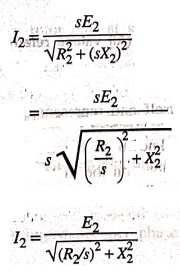
From the above
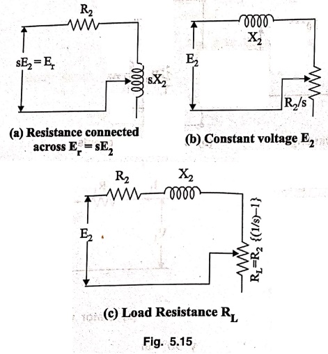
relation, it appears that the rotor circuit consists of a fixed resistance, R2
and a variable reactance sX2 (proportional to slip) connected across
Er = sE2 as shown in Fig. 5.15 (a). This can also be
stated that the rotor circuit is having fixed reactance X2 connected
in series with a variable resistance R0/s (inversely proportional to
slip) and supplied with constant voltage E2 as shown in Fig. 5.15
(b).
Now the resistance, R2/s
= (R2+ R2/s) − R2
R2/s = R2+ R2
[(1/s) ‒ 1]
It consists of 2 parts,
• The first part R2
is the rotor resistance itself and represents the copper loss.
• The second part is R2[(1/s)
‒ 1]. This is known as the load resistance RL and is the electrical
equivalent of the mechanical load on the motor. The equivalent circuit of the
rotor along with the load resistance RL may be drawn as in Fig. 5.15
(c).
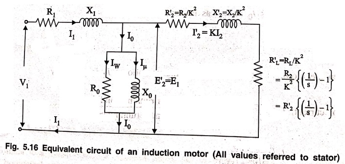
As in the case of
transformer, in this case also the secondary values may be transferred to primary
and vice versa. When shifting impedance / resistance from secondary to primary,
it should be divided by K2, whereas current should be multiplied by
K where K is the transformation ratio.
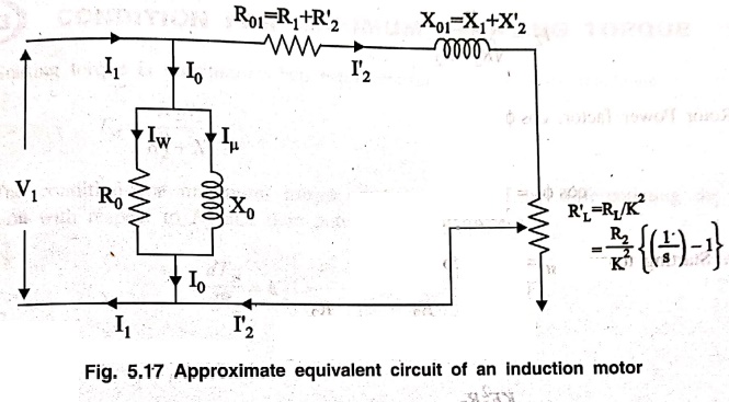
The approximate
equivalent circuit is obtained by shifting the exciting circuit to the left.
The calculations with this modified circuit is also simplified.
Basic Electronics and Electrical Engineering: Chapter 5: Induction Motors : Tag: Basic Engineering : - Equivalent Circuit of Three Phase Induction Motor
Basic Electronics and Electrical Engineering: Chapter 5: Induction Motors
Under Subject

Basic Electronics and Electrical Engineering
EE25C04 1st Semester ECE Dept | 2025 Regulation | 2nd Semester 2025 Regulation
Related Subjects

English Essentials I
EN25C01 1st Semester | 2025 Regulation | 1st Semester 2025 Regulation

தமிழர் மரபு - Heritage of Tamils
UC25H01 1st Semester | 2025 Regulation | 1st Semester 2025 Regulation
Applied Calculus
MA25C01 Maths 1 M1 - 1st Semester | 2025 Regulation | 1st Semester 2025 Regulation
Applied Physics I
PH25C01 1st Semester | 2025 Regulation | 1st Semester 2025 Regulation

Applied Chemistry I
CY25C01 1st Semester | 2025 Regulation | 1st Semester 2025 Regulation
Makerspace
ME25C04 1st Semester | 2025 Regulation | 1st Semester 2025 Regulation
Computer Programming C
CS25C01 1st Semester | 2025 Regulation | 1st Semester 2025 Regulation
Computer Programming Python
CS25C02 1st Semester | 2025 Regulation | 1st Semester 2025 Regulation
Fundamentals of Electrical and Electronics Engineering
EE25C03 1st Semester | 2025 Regulation | 1st Semester 2025 Regulation
Introduction to Mechanical Engineering
ME25C03 1st Semester | 2025 Regulation | 1st Semester 2025 Regulation

Introduction to Civil Engineering
CE25C01 1st Semester Civil Department | 2025 Regulation | 1st Semester 2025 Regulation
Essentials of Computing
CS25C03 1st Semester - AID CSE IT Department | 2025 Regulation | 1st Semester 2025 Regulation

Applied Physics I Laboratory
PH25C01 1st Semester practical Laboratory Manual | 2025 Regulation | 1st Semester Laboratory 2025 Regulation

Applied Chemistry I Laboratory
CY25C01 1st Semester practical Laboratory Manual | 2025 Regulation | 1st Semester Laboratory 2025 Regulation

Computer Programming C Laboratory
CS25C01 1st Semester practical Laboratory Manual | 2025 Regulation | 1st Semester Laboratory 2025 Regulation

Computer Programming Python Laboratory
CS25C02 1st Semester practical Laboratory Manual | 2025 Regulation | 1st Semester Laboratory 2025 Regulation
Engineering Drawing
ME25C01 EEE Mech Dept | 2025 Regulation | 2nd Semester 2025 Regulation
Basic Electronics and Electrical Engineering
EE25C04 1st Semester ECE Dept | 2025 Regulation | 2nd Semester 2025 Regulation