Computer Organization and Architecture: Chapter 1: Introduction
Functional Units of Computer
Questions: 1. Explain different functional units of a digital computer. 2.What is a stored program concept? Explain the functional units of a stored program digital computer, along with a block diagram. 3. Draw block diagram of a basic processor. 4.What are the special registers in a typical computer? Explain their purposes in detail. 5. Define IR and MAR.
Chapter 1:
Introduction
Functional Units
•
The digital computer or simply computer in its simplest form is a fast
electronic calculating machine that accepts digitized information from the
user, processes it according to a sequence of instructions stored in the
internal storage and provides the processed information to the user.
•
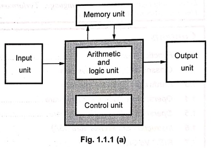
The computer consists of five functionally independent units:
■
Input
■
Memory
■
Arithmetic and logic
■
Output and
■
Control units.
•
Fig. 1.1.1 (a) and (b) show these five functional units of a computer and its
physical locations in the computer.
•
The input unit accepts the digital information from user with the help of input
devices such as keyboard, mouse, microphone etc..
•
The information received from the input unit is either stored in the memory for
later use or immediately used by the arithmetic and logic unit to perform the
desired operations.

•
The program stored in the memory decides the processing steps and the processed
output is sent to the user with the help of output devices or it is stored in
the memory for later reference.
•
All the above mentioned activities are co‒ordinated and controlled by the
control unit.
•
The arithmetic and logic unit in conjunction with control unit is commonly
called Central Processing Unit (CPU).
1. Input Unit
•
A computer accepts a digitally coded information through input unit using input
devices.
•
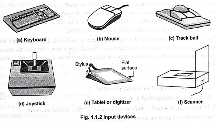
The most commonly used input devices are keyboard and mouse.
•
The keyboard is used for entering text and numeric information.
•
Mouse is used to position the screen cursor and thereby enter the information
by selecting option.
•
Apart from keyboard and mouse there are many other input devices are available,
which include joysticks, trackball, spaceball, digitizers and scanners.
2. Memory Unit
•
The memory unit is used to store programs and data.
•
Usually, two types of memory devices are used to form a memory unit: Primary storage memory device and secondary storage memory device.
•
The primary memory, commonly called main
memory is a fast memory used for the storage of programs and active data
(the data currently in process).
•
The main memory is a semiconductor memory.
•
It consists of a large number of semiconductor storage cells, each capable of
storing one bit of information.
•
These cells are read or written by the central processing unit in a group of
fixed size called word.
•
The main memory is organized such that the contents of one word, containing n
bits, can be stored or retrieved in one write or read operation, respectively.
•
To access data from a particular word from main memory each word in the main
memory has a distinct address. This
allows to access any word from the main memory by specifying corresponding
address.
•
The number of bits in each word is referred to as the word length of the computer. Typically, the word length varies from
8 to 64 bits.
•
The number of such words in the main memory decides the size of memory or capacity of the memory.
•
The size of computer main memory varies from few million words to tens of million
words.
•
An important characteristics of a memory is an access time (the time required
to access one word). The access time for main memory should be as small as
possible. Typically, it is of the order of 10 to 100 nanoseconds. The access
time depends on the type of memory. In Randomly Accessed Memories (RAMs), fixed
time is required to access any word in the memory. In sequential access
memories this time is not fixed.
•
The main memory consists of only randomly accessed memories. These memories are
fast but they are small in capacities and expensive. Therefore, the computer
uses the secondary storage memories such as magnetic tapes, magnetic disks for
the storage of large amount of data.
Stored program concept
•
Today's computer are built on two key principles
1.
Instructions are represented as numbers.
2.
Programs can be stored in memory to be read or written just like numbers.
•
These principles lead to the stored‒program concept.
•
According to stored‒program concept, memory can contain the program (source
code), the corresponding compiled machine code, editor program and even the
compiler that generated the machine code.
3. Arithmetic and Logic Unit
•
The arithmetic and logic unit (ALU) is responsible for performing arithmetic
operations such as add, subtract, division and multiplication and logical
operations such as ANDing, ORing, Inverting etc.
•
To perform these operations, operands from the main memory are brought into the
high speed storage elements called
registers of the processor.
•
Each register can store one word of data and they are used to store frequently
used operands.
•
After performing operation, the result is either stored in the register or
memory location.
4. Output Unit
•
The output unit sends the processed results to the user using output devices
such as video monitor, printer, plotter, etc.
•
The video monitors display the output on the CRT screen whereas printers and
plotters give the hard‒copy output.
•
Printers are classified according to their printing methodology: Impact printers and non‒ impact printers.
5. Control Unit
•
The control unit co‒ordinates and controls the activities amongst the
functional units.
•
Control unit fetches the instructions stored in the main memory, identify the
operations and the devices involved in it and accordingly generate control
signals to execute the desired operations.
•
It uses control signals or timing signals to determine when a given action is
to take place.
•
It controls input and output operations, data transfers between the processor,
memory and input/output devices using timing signals.
•
The control and the arithmetic and logic units of a computer are usually many
times faster than other devices connected to a computer system. This enables
them to control a number of external input/output devices.
6. Basic Operational Concepts
•
The basic function of computer is to execute program, sequence of instructions.
•
Instructions are stored in the computer memory.
•
Instructions are executed to process data which is loaded into the computer
memory through input unit.
•
After processing the data, the result is either stored back into the computer
memory for further reference or it is sent to the outside world through the
output port.
•
All functional units of the computer contribute to execute a program.
•
The functions of different computer units are,
■ The input unit accepts data and instructions
from the outside world to machine. It is operated by control unit.
■ The memory unit stores both, data and
instructions.
■ The arithmetic‒logic unit performs
arithmetic and logical operations.
■ The control unit fetches and interprets the
instructions in memory and causes them to be executed.
■ The output unit transmits final results and
messages to the outside world.
•
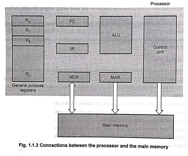
To perform execution of instruction, the processor contains a number of
registers used for temporary storage of data and some special function
registers, as shown in Fig. 1.1.3.
•
The special function registers include Program Counter (PC), Instruction
Register (IR), Memory Address Register (MAR) and Memory Data Register (MDR).
Program Counter (PC):
•
A program is a series of instructions stored in the memory. These instructions tell
the CPU exactly how to get the desired result.
•
It is important that these instructions must be executed in a proper order to
get the correct result.
•
The sequence of instruction execution is monitored by the program counter.
•
It keeps track of which instruction is being executed and what the next
instruction will be.
Instruction Register (IR):
•
It is used to hold the instruction that is currently being executed.
•
The contents of IR are available to the control unit, which generate the timing
signals that control the various processing elements involved in executing the
instruction.
Memory Address Register (MAR) and Memory Data Register (MDR):
•
These registers are used to handle the data transfer between the main memory
and the processor.
•
The MAR holds the address of the main memory to or from which data is to be
transferred.
•
The MDR sometimes also called MBR
(Memory Buffer Register) contains the data to be written into or read from
the addressed word of the main memory.
General Purpose Registers:
•
These are used to hold the operands for
arithmetic and logic operations and/or used to store the result of the
operation.
•
Since the access time of these registers is lowest, these are used to store frequently used data.
Execution of Program:
•
PC is set to point to the first instruction of the program.
•
The contents of PC are transferred to the MAR, whose output is connected to the
address lines of memory, and simultaneously read control signal is sent to the
memory.
•
After the access time of memory, the addressed word is received from memory and
stored into the MDR.
•
The received instruction code, i.e. the contents of MDR are transferred to IR
and now instruction is ready to be decoded and executed.
•
If the instruction involved an operation to be performed by the ALU and operand
is available in general‒purpose registers the operation is performed by the
ALU.
•
If operand is not available in the general‒purpose registers, it is reside in
the memory. It has to be fetched by sending its address to the MAR and
initiating a read cycle.
•
When the operand is read from the memory into the MDR, it is transferred from
the MDR to the ALU.
•
ALU then performs the desired operation and stores the result either in the
general purpose registers or in the memory.
•
If the result of operation is to be stored in the memory, then the result is
sent to the MDR. The address of the memory location where the result is to be
stored is sent to the MAR and a write cycle is initiated.
•
During the execution of current instruction, the contents of PC are incremented
so that they points to the next instruction to be executed.
•
As soon as current instruction is executed, next instruction is fetched and
cycle is repeated.
•
Like memory, computer also communicates with input/output devices. Thus,
computer also has some instruction to handle I/O data transfer.
Concept of Interrupt and Interrupt Service Routine (ISR):
•
Sometimes it is necessary to have computer system which can automatically execute
one of the collection of special routines whenever certain conditions exist
within a program or in the computer system.
•
For example, it is necessary that computer system should give response to
devices such as keyboard, sensor and other components when they request for
service.
•
In order to deal with the situation, the normal execution of program must be
interrupted. To do this, devices use interrupt signal.
•
By activating an interrupt signal I/O device request for the service.
•
In response to an interrupt processor executes an appropriate Interrupt‒Service Routine (ISR).
•
After execution of ISR processor resumes the execution of program which was
interrupted.
•
The execution of ISR may alter the internal state of the processor (contents of
PC, the general purpose registers and some control information) and hence it
must be stored in memory before servicing the interrupt.
•
When the interrupt service routine is completed, the state of the processor is
restored.
Example:1
State the operations involved in
the execution of ADD R1, RO instruction.
Solution:
The instruction Add R1, R0 adds the operand in R1 register to the operand in R0
register and stores the sum into R0 register. Let us see the steps involved in
the execution of this instruction.
1.
Fetch the instruction from the memory into IR register of the processor.
2.
Decode the instruction.
3.
Add the contents of R1 and R0 and store the result in the R0
Example:2
State the operations involved in
the execution of Add LOCA. R0.
Solution:
The instruction Add LOCA, R0 adds the operand at memory location LOCA to the
operand in register R0 and stores result in the register R0. The steps involved
in the execution of this instruction are:
1.
Fetch the instruction from the memory into the IR register of the processor.
2.
Decode the instruction.
3.
Fetch the second operand from memory location LOCA and add the contents of LOCA
and the contents of register R0.
4.
Store the result in the R0.
Review Questions
1. Explain different
functional units of a digital computer.
2.What is a stored
program concept? Explain the functional units of a stored program digital
computer, along with a block diagram.
3. Draw block diagram
of a basic processor.
4.What are the special
registers in a typical computer? Explain their purposes in detail.
5. Define IR and MAR.
Computer Organization and Architecture: Chapter 1: Introduction : Tag: Computer : - Functional Units of Computer
Computer Organization and Architecture: Chapter 1: Introduction
Under Subject
Computer Organization and Architecture
CW25201 3rd Semester IT department. | 2025 Regulation | 3rd Semester 2025 Regulation
Related Subjects
Discrete Mathematics
MA25C14 3rd Semester CSE,IT,CY,AIDS departments. | 2025 Regulation | 3rd Semester 2025 Regulation
Data Structures
CS25C08 3rd Semester CSE,IT,CY,AIDS departments. | 2025 Regulation | 3rd Semester 2025 Regulation
Computer Organization and Architecture
CW25201 3rd Semester IT department. | 2025 Regulation | 3rd Semester 2025 Regulation
Object Oriented Programming
CS25C07 3rd Semester IT department. | 2025 Regulation | 3rd Semester 2025 Regulation
Web Technologies
IT25301 3rd Semester IT department. | 2025 Regulation | 3rd Semester 2025 Regulation
English Communication Skills Laboratory I
EN25C03 3rd Semester all department. | 2025 Regulation | 3rd Semester 2025 Regulation
Skill Development Course I
3rd Semester all department. | 2025 Regulation | 3rd Semester 2025 Regulation