Basic Electronics and Electrical Engineering: Chapter 5: Induction Motors
Making Single Phase Induction Motor Self Starting
A single phase motor is very similar to a 3‒phase squirrel cage induction motor. It has (i) a squirrel‒cage rotor identical to a 3‒phase motor and (ii) a single‒phase winding on the stator.
MAKING
SINGLE PHASE INDUCTION MOTOR SELF‒STARTING
A single phase motor is
very similar to a 3‒phase squirrel cage induction motor. It has (i) a squirrel‒cage
rotor identical to a 3‒phase motor and (ii) a single‒phase winding on the stator.
Unlike a 3‒phase
induction motor, a single‒phase induction motor is not self‒starting but
requires some starting means. The single‒phase stator winding produces a
magnetic field that pulsates in strength in a sinusoidal manner. The field polarity
reverses after each half cycle but the field does
not rotate. Consequently, the alternating flux cannot produce rotation in
a stationary squirrel‒cage rotor. However, if the rotor of a single‒phase motor
is rotated in one direction by some mechanical means, it will continue to run
in the direction of rotation. As a matter of fact, the rotor quickly
accelerates until it reaches a speed slightly below the synchronous speed. Once
the motor is running at this speed, it will continue to rotate even though single‒phase
current is flowing through the stator winding. This method of starting is
generally not convenient for large motors. Nor can it be employed for a motor
located at some inaccessible spot.
Making self‒starting
To make a single‒phase
induction motor self‒starting, we should somehow produce a revolving stator
magnetic field. This may be achieved by converting a single‒phase supply into
two phase supply through the use of an additional winding. When the motor
attains sufficient speed, the starting winding (i.e., additional winding) may
be removed depending upon the type of the motor. As a matter of fact, single‒phase
induction motors are classified and named according to the means employed to
make them self‒starting.
(i)
Split‒phase motors - started by two‒phase motor action
through the use of an auxiliary or starting winding.
(ii)
Capacitor motors - started by the motion of the magnetic
field through the use of an auxiliary winding and a capacitor.
(iii)
Shaded‒pole motors - started by the motion of the magnetic
field produced by means of a shading coil around a portion of the pole
structure.
1. Double‒field Revolving Theory
This theory makes use
of the idea that an alternating uni‒axial quantity can be represented by 2
oppositely ‒ rotating vectors of half magnitude. Accordingly, an alternating
sinusoidal flux can be represented by 2 revolving fluxes, each equal to half
the value of the alternating flux and each rotating synchronously in opposite
direction.
As shown in Fig. 5.26
(a) let the alternating flux have a maximum value of ϕm. Its
component fluxes A and B will each be equal to ϕm/2, revolving in
anticlockwise and clockwise directions respectively. After some time, when A
and B would have rotated through angle +θ and –θ in Fig. 5.26 (b), the
resultant flux would be = 2 θm/2 cos(2θ /2) = θm cosθ.
After a quarter cycle
of rotation, fluxes A and B will be oppositely directed as shown in Fig. 5.26
(c) so that the resultant flux will be zero [Fig. 5.26 (d)]. After half a
cycle, fluxes A and B will have a resultant of ‒2 × ϕm/2 = ‒ϕm. After 3 quarters of a cycle,
again the resultant is zero, as shown in Fig. 5.26 (e). and so on.
If we plot the values
of resultant flux against θ between limits θ = 0° to θ = 360°, then a curve similiar to the
one shown in Fig. 5.26 (f) is obtained. That is why an alternating flux can be
looked upon as composed of 2 revolving fluxes, each of half the value revolving
synchronously in opposite directions.

2. Torque ‒ Slip Characteristics
It may be noted that if
the slip of the rotor is s with respect to the forward rotating flux [i.e., one
which rotates in the same direction as rotor], then its slip with respect to
the backward rotating flux is (2 ‒ s). It may be proved thus
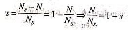
If N is the r.p.m of
the rotor, then its slip with respect to forward rotating flux is
s = (NS‒N) /
NS = 1 ‒ N/NS
N/NS = 1 ‒ s
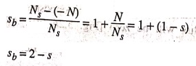
Keeping in mind the
fact that the backward rotating flux rotates opposite to the rotor, the rotor
slip with respect to this flux is
sb= (NS‒(‒N))
/ NS = 1 ‒ N/NS
N/NS = 1 + (1 ‒ s)
sb = 2 ‒ s
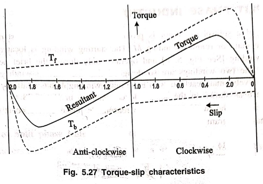
Each of the 2 component
fluxes, while revolving round the stator, cuts the rotor, induces an emf and
this produces its own torque. Obviously the 2 torques are oppositely directed,
so that the net / resultant torques is equal to their difference as shown in
Fig. 5.27.
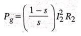
Now, power developed by
a rotor, is
If N is the rotor
r.p.s. then torque is given by
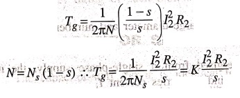
Hence the forward and
backward torques are given by
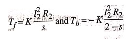
Total torque T = Tƒ + Tb
Fig. 5.27 shows both
torques and the resultant torque for slips between 0 to 2. At standstill s = 1
and 2‒s=1. Hence. Tf and Tb are numerically equal, but,
being oppositely directed, produce no resultant torque. That explains why there
is no starting torque in a single phase motor.
However if the rotor is
started somehow, say in the clockwise direction, the clockwise torque starts
increasing and, at the same time, the anticlockwise torque starts decreasing.
Hence there is a certain amount of net torque in clockwise direction
accelerating the motor to full speed.
Basic Electronics and Electrical Engineering: Chapter 5: Induction Motors : Tag: Basic Engineering : - Making Single Phase Induction Motor Self Starting
Basic Electronics and Electrical Engineering: Chapter 5: Induction Motors
Under Subject

Basic Electronics and Electrical Engineering
EE25C04 1st Semester ECE Dept | 2025 Regulation | 2nd Semester 2025 Regulation
Related Subjects

English Essentials I
EN25C01 1st Semester | 2025 Regulation | 1st Semester 2025 Regulation

தமிழர் மரபு - Heritage of Tamils
UC25H01 1st Semester | 2025 Regulation | 1st Semester 2025 Regulation

Applied Calculus
MA25C01 Maths 1 M1 - 1st Semester | 2025 Regulation | 1st Semester 2025 Regulation

Applied Physics I
PH25C01 1st Semester | 2025 Regulation | 1st Semester 2025 Regulation

Applied Chemistry I
CY25C01 1st Semester | 2025 Regulation | 1st Semester 2025 Regulation

Makerspace
ME25C04 1st Semester | 2025 Regulation | 1st Semester 2025 Regulation

Computer Programming C
CS25C01 1st Semester | 2025 Regulation | 1st Semester 2025 Regulation

Computer Programming Python
CS25C02 1st Semester | 2025 Regulation | 1st Semester 2025 Regulation

Fundamentals of Electrical and Electronics Engineering
EE25C03 1st Semester | 2025 Regulation | 1st Semester 2025 Regulation

Introduction to Mechanical Engineering
ME25C03 1st Semester | 2025 Regulation | 1st Semester 2025 Regulation

Introduction to Civil Engineering
CE25C01 1st Semester Civil Department | 2025 Regulation | 1st Semester 2025 Regulation

Essentials of Computing
CS25C03 1st Semester - AID CSE IT Department | 2025 Regulation | 1st Semester 2025 Regulation

Applied Physics I Laboratory
PH25C01 1st Semester practical Laboratory Manual | 2025 Regulation | 1st Semester Laboratory 2025 Regulation

Applied Chemistry I Laboratory
CY25C01 1st Semester practical Laboratory Manual | 2025 Regulation | 1st Semester Laboratory 2025 Regulation

Computer Programming C Laboratory
CS25C01 1st Semester practical Laboratory Manual | 2025 Regulation | 1st Semester Laboratory 2025 Regulation

Computer Programming Python Laboratory
CS25C02 1st Semester practical Laboratory Manual | 2025 Regulation | 1st Semester Laboratory 2025 Regulation

Engineering Drawing
ME25C01 EEE Mech Dept | 2025 Regulation | 2nd Semester 2025 Regulation
Basic Electronics and Electrical Engineering
EE25C04 1st Semester ECE Dept | 2025 Regulation | 2nd Semester 2025 Regulation