Electron Devices: Chapter 4: Bipolar Junction Transistors
Multi-Emitter Transistors
Questions: 1. Write a note on multi‒emitter transistor. 2. What is the main advantage of multi‒emitter transistor? 3. What is multiple emitter transistor? Draw the symbol of that. 4. State the applications of multi‒emitter transistor.
Multi‒Emitter
Transistors
•
Component density of an integrated circuit (IC) is enhanced by the efficient
utilization of the chip area.
•
Merged transistors, that is two or more devices which share one or more common
regions, provide one method of space saving on a chip. The most widely used
merged transistor is the multiple‒emitter transistor.
•
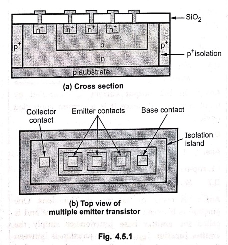
Fig. 4.5.1 (a) shows the cross‒section of multi‒emitter bipolar npn transistor.
As shown in Fig. 4.5.1 (a), multi‒emitters are normally fabricated within the
same base region. Each emitter stripe can be considered as the emitter of a
separate transistor.
•
Fig. 4.5.1 (b) shows the top view of multiple emitter transistor.
•
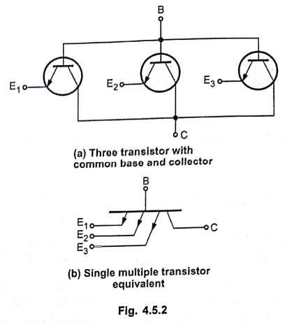
Fig. 4.5.2 shows three transistors with common collector and base terminals and
its single multiple emitter transistor equivalent. In this construction each
transistor shares a common base and collector.
• Multi‒emitter transistor is the basis of of the Transistor‒Transistor Logic (TTL).
•
Multiple‒emitter transistors have been fabricated with more than 60 emitter
stripes.
Applications of Multi‒Emitter Transistors
1. Primary application ‒ Transistor‒Transistor Logic (TTL)
•
The most common and important application of a multi‒emitter transistor is in
the input stage of TTL logic gates, especially in the NAND gate configuration.
Each emitter acts as an independent input line.
•
Function: The transistor performs
the NAND logic function efficiently. If any one emitter receives a LOW signal,
it pulls the base low, cutting off collector current and driving the output
LOW.
•
Advantage: This design eliminates
the need for multiple input diodes (as used in earlier Diode‒Transistor Logic,
DTL), providing faster switching speed, lower propagation delay and better
circuit compactness. Hence, multi‒emitter transistors are the key elements that
make TTL logic families faster and more efficient.
2. In Digital Integrated Circuits (ICs)
•
Multi‒emitter transistors are extensively used in digital IC design due to
their compact and multi‒input structure. By integrating multiple inputs into a
single transistor, the total component count, chip area, and interconnection
delay are significantly reduced.
•
This leads to high‒speed and reliable operation in devices such as counters,
registers, microcontrollers, and processors.
3. In Input Interface Circuits
•
In microprocessors, microcontrollers, and programmable logic devices, multi‒emitter
transistors are used in input interface sections.
•
They enable simultaneous sensing and processing of several incoming digital
control or data signals, ensuring efficient communication and signal handling
between different digital modules.
4. In Specialized Circuits
•
Although less common, multi‒emitter transistors can also be used in specialized
high‒frequency or high‒power circuits.
•
In such cases, multiple emitters may be connected in parallel to distribute the
emitter current evenly, improving current‒handling capability and high‒speed
performance.
•
They are also used in certain bipolar semiconductor memory architectures for
addressing and control functions, where multiple input lines must be managed by
a single transistor device.
Review
Questions
1. Write a note on multi‒emitter transistor.
2. What is the main advantage of multi‒emitter transistor?
3. What is multiple emitter transistor? Draw the symbol of that.
4. State the applications of multi‒emitter transistor.
Electron Devices: Chapter 4: Bipolar Junction Transistors : Tag: electronics : - Multi-Emitter Transistors
Electron Devices: Chapter 4: Bipolar Junction Transistors
Under Subject

Electron Devices
EC25C01 2nd Semester ECE Dept | 2025 Regulation | 2nd Semester 2025 Regulation
Related Subjects

English Essentials II
EN25C02 2nd Semester | 2025 Regulation | 2nd Semester 2025 Regulation

Tamils and Technology தமிழர்களும் தொழில்நுட்பமும்
UC25H02 2nd Semester | 2025 Regulation | 2nd Semester 2025 Regulation

Linear Algebra
MA25C02 2nd Semester | 2025 Regulation
Electron Devices
EC25C01 2nd Semester ECE Dept | 2025 Regulation | 2nd Semester 2025 Regulation

Data Structures using CPlusPlus
CS25C05 2nd Semester ECE Dept | 2025 Regulation | 2nd Semester 2025 Regulation

Circuits and Network Analysis
EC25C02 2nd Semester ECE Dept | 2025 Regulation | 2nd Semester 2025 Regulation

Re-Engineering for Innovation
ME25C05 2nd Semester | 2025 Regulation | 2nd Semester 2025 Regulation

Engineering Drawing - Laboratory
ME25C01 2nd Semester | 2025 Regulation | 2nd Semester 2025 Regulation

Data Structures using CPlusPlus - Laboratory
CS25C05 2nd Semester ECE Dept | 2025 Regulation | 2nd Semester 2025 Regulation

Devices and Circuits Laboratory
EC25C03 2nd Semester ECE Dept | 2025 Regulation | 2nd Semester 2025 Regulation