Basic Electronics and Electrical Engineering: Chapter 5: Induction Motors
Starting of Induction Motors
When the 3‒phase supply is connected to the stator of a three‒phase induction motor, a rotating magnetic field is produced and the rotor starts rotating.
STARTING
OF INDUCTION MOTORS
When the 3‒phase supply
is connected to the stator of a three‒phase induction motor, a rotating
magnetic field is produced and the rotor starts rotating. Thus, a three‒phase
induction motor is self‒starting. At the time of starting the motor slip is
unity and the starting torque is very large. The purpose of a starter is not
only to start the motor but it also performs the following functions:
(i) Reduction of the
heavy starting current
(ii) Overload and no‒load
protection
In general, 3‒phase
induction motors may be started either by connecting the mote directly to the
full voltage of the supply or by applying a reduced voltage to the motor
starting period. The torque of an induction motor is proportional to the square
of the applied voltage. Thus, a greater torque is exerted by a motor when it is
started on full voltage than when it is started on reduced voltage.
Some of the starters for starting induction
motors are discussed below:
Squirrel Cage Induction Motors
The following are the
commonly used starters for cage motors.
1. Direct‒online
starter
2. Star‒Delta starter
3. Auto transformer
starter
1. Direct‒online Starter
In the direct on line
method of starting cage motors, the motor is directly connected to the 3‒phase
supply. Fig. 5.22, shows the connection for direct‒on‒line [D.O.L] Starter.
It consists of a coil‒operated
contactor C controlled by start and stop push button switch which may be
installed at convenient places remote from the starter. On pressing the START
push button S1, the contactor coil C is energised from two line
conductors L1 and L2. The three main contacts M and the
auxiliary contact A close and the terminals a and b are short‒circuited.

The motor is thus
connected to the supply. When the pressure on S1 is released, it
moves back under spring action. Even then the coil C remains energised through ab. Thus, the main contacts M remain
closed and the motor continues to get supply. For this reason, contact A is
called hold‒on‒contact.
When the stop button S2
is pressed, the supply through the contactor coil C is disconnected. Since the
coil C is de‒energised, the main contacts M and auxiliary contact A are opened.
The supply to the motor is disconnected and the motor stops.
2. Star‒Delta Starter
A Star‒Delta starter is
used for cage motors designed to run normally on delta connected stator
winding. Fig [5.23 (a)] shows the connections of a 3‒phase induction motor with
a Star‒Delta starter. When the switch 's' is in the START position, the stator
windings are connected in STAR Fig. [5.23 (b)]. When the motor picks up speed,
say 80% of its rated value, the change over switch is thrown quickly to the RUN
position which connects the stator windings in DELTA [Ref Fig. 5.23 (c)].

By connecting the
stator windings, first in star and then in delta, the line current drawn by the
motor at starting is reduced to 1/3rd as compared to starting
current with the windings connected in delta. At the time of starting when the
stator windings are star connected, each stator phase sets a voltage VL/√3
where VL is is the line voltage. Since the torque developed by an
induction motor is proportional to the square of the applied voltage, star‒delta
starting reduces the starting torque to 1/3rd of that obtained by
direct‒delta starting.
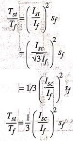
Relation
between Tst and Tf
Ist per phase 1/√3Isc
per phase
where, Isc
is the current per phase which delta‒connected motor would have taken if
switched on to the supply directly.
However, the line
current at start is equal to 1/√3 of line current, Isc
Starting torque,
Tst ∝ Ist2 at s=1 ………….. (5.29)
Full‒load torque,
Tf ∝ If2/sf
………….. (5.30)
Eqn (5.29) divided by
eqn (5.30), will give,
This type of starters
are employed for starting 3‒phase squirrel cage motors of rating between 4 and
20 kW.
3. Auto Transformer Starter
An auto transformer
starter is suitable for both Star and Delta connected motors. In this method,
the starting current is limited by using a 3‒phase auto transformer to reduce
initial stator applied voltage. Fig. 5.24 shows the motor with the auto‒transformer
starter. The auto transformer is provided with a number of tapping
arrangements.
Here, a double throw
switch is used to connect the auto‒transformer in the circuit for starting.
When the handle H of the switch is in the START position, the primary of the
auto transformer is connected to the supply line and the motor is connected to
the secondary of the auto‒transformer.
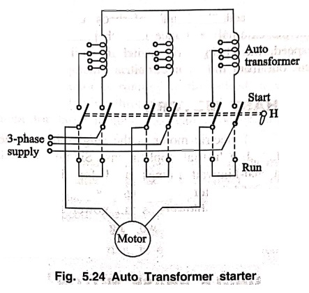
When the motor picks up
speed, say to about 80% of its rated value, the handle H is quickly moved to
the RUN position, the auto‒transformer is disconnected from the circuit and the
motor is directly connected to the line and gets its full rated voltage. The
handle is held in the RUN position by the under‒voltage relay. In case the
supply voltage fails or falls below a certain value, the handle is released and
returns to the OFF position.
Slip Ring Motor
1. Rotor rheostat
starter
1. Rotor - Resistance Starter [Slip‒ring Motor Starter]
In this method, a
variable star‒connected rheostat is connected in the rotor circuit through slip‒rings
and full voltage is applied to the stator winding as shown in Fig. 5.2
At starting period, the
handle of rheostat is set in the OFF position so that maximum resistance is
placed in each phase of the rotor circuit. This reduces the starting current
and at the same time starting torque is increased.
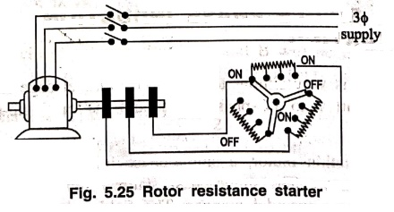
As the motor picks up
speed, the handle of rheostat is gradually moved in clockwise direction which
cuts out the external resistance in each phase of the rotor circuit. When the motor
attains normal speed, the change‒over switch is in the ON position and the
whole external resistance is cut out from the rotor circuit.
Basic Electronics and Electrical Engineering: Chapter 5: Induction Motors : Tag: Basic Engineering : - Starting of Induction Motors
Basic Electronics and Electrical Engineering: Chapter 5: Induction Motors
Under Subject

Basic Electronics and Electrical Engineering
EE25C04 1st Semester ECE Dept | 2025 Regulation | 2nd Semester 2025 Regulation
Related Subjects

English Essentials I
EN25C01 1st Semester | 2025 Regulation | 1st Semester 2025 Regulation

தமிழர் மரபு - Heritage of Tamils
UC25H01 1st Semester | 2025 Regulation | 1st Semester 2025 Regulation

Applied Calculus
MA25C01 Maths 1 M1 - 1st Semester | 2025 Regulation | 1st Semester 2025 Regulation

Applied Physics I
PH25C01 1st Semester | 2025 Regulation | 1st Semester 2025 Regulation

Applied Chemistry I
CY25C01 1st Semester | 2025 Regulation | 1st Semester 2025 Regulation

Makerspace
ME25C04 1st Semester | 2025 Regulation | 1st Semester 2025 Regulation

Computer Programming C
CS25C01 1st Semester | 2025 Regulation | 1st Semester 2025 Regulation

Computer Programming Python
CS25C02 1st Semester | 2025 Regulation | 1st Semester 2025 Regulation

Fundamentals of Electrical and Electronics Engineering
EE25C03 1st Semester | 2025 Regulation | 1st Semester 2025 Regulation

Introduction to Mechanical Engineering
ME25C03 1st Semester | 2025 Regulation | 1st Semester 2025 Regulation

Introduction to Civil Engineering
CE25C01 1st Semester Civil Department | 2025 Regulation | 1st Semester 2025 Regulation

Essentials of Computing
CS25C03 1st Semester - AID CSE IT Department | 2025 Regulation | 1st Semester 2025 Regulation

Applied Physics I Laboratory
PH25C01 1st Semester practical Laboratory Manual | 2025 Regulation | 1st Semester Laboratory 2025 Regulation

Applied Chemistry I Laboratory
CY25C01 1st Semester practical Laboratory Manual | 2025 Regulation | 1st Semester Laboratory 2025 Regulation

Computer Programming C Laboratory
CS25C01 1st Semester practical Laboratory Manual | 2025 Regulation | 1st Semester Laboratory 2025 Regulation

Computer Programming Python Laboratory
CS25C02 1st Semester practical Laboratory Manual | 2025 Regulation | 1st Semester Laboratory 2025 Regulation

Engineering Drawing
ME25C01 EEE Mech Dept | 2025 Regulation | 2nd Semester 2025 Regulation
Basic Electronics and Electrical Engineering
EE25C04 1st Semester ECE Dept | 2025 Regulation | 2nd Semester 2025 Regulation