Basic Electronics and Electrical Engineering: Chapter 5: Induction Motors
Speed Control of Induction Motors
We can control the speed of the 3ϕ induction motor, by the following methods: I. Control from stator side II. Control from rotor side
SPEED
CONTROL OF INDUCTION MOTORS
We can control the
speed of the 3ϕ induction motor, by the following methods:
I. Control from stator side
1. By changing the
applied voltage
2. By changing the
supply frequency
3. By changing the
number of stator poles
1. Changing applied voltage
This method, though
cheapest and easiest, is rarely used because a large change in voltage is required
for a relatively small change in speed. This large change in voltage will
result in a large change in the flux density thereby seriously disturbing the
magnetic conditions of the applied frequency.
2. Changing the supply frequency
This method is also
used rarely. We have seen that the synchronous speed of an induction motor is
given by,
NS = 120f / P
Clearly, the
synchronous speed of an induction motor can be changed by changing the supply
frequency 'f '. This method has been
used to some extent on electrically‒driven ships.
3. By changing the number of Stator poles
This méthod is easily
applicable to squirrel cage motors because the squirrel cage rotor adapts
itself to any reasonable number of stator poles. From the synchronous speed
equation, NS = 120ƒ / p, it is evident that the speed of an
induction motor could also be changed by changing the number of stator poles.
This change of number of poles is achieved by having two or more entirely
independent stator windings in the same slot. Each winding gives a different
number of poles and hence different synchronous speed.
II Control from rotor side
1. Rotor rheostat
control
2. By operating two
motors in cascade (Concatenation Method)
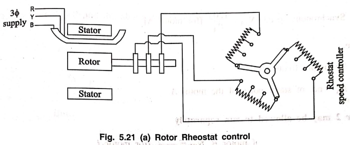
1. Rotor Rheostat Control
In this method, which
is applicable only for slipring induction motor, the motor speed is reduced by
introducing an external resistance in the rotor circuit. [Ref Fig. 5.21(a)].
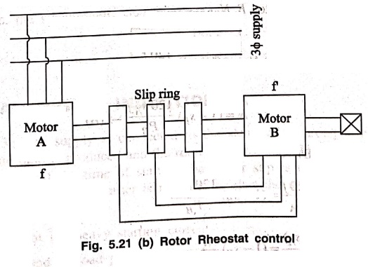
2. Cascade / Concatenation / Tandem operation
This method requires 2
motors, the first of which must have a wound rotor. It should also have a one‒to‒one
voltage ratio. So that in addition to cascading, each motor may be run from the
supply mains separately. That is, at standstill with rotor circuit open, the
voltage across the slip‒rings should be equal to that across the stator
terminals. The stators of both motors should be wound for the same voltage. The
second motor may be of the squirrel cage type or have a wound rotor with
external resistance. The rotor shafts are directly coupled, so that both run at
the same speed.
The stator of the first
motor, A is connected to the 3‒ϕ supply. Then the rotor of the first motor is
connected to the stator of the second motor B. The starting resistance is
connected to the rotor circuit of the second motor
In cascade method,
there are 4 ways to obtain different speeds by the combination of motors.
Motor
1 may be run separately from the supply,
Synchronous speed, NSA
= 120f / PA [for motor A]
Where,
f = supply frequency
PA = no. of
stator poles of the motor A
Motor
2 may be allowed to run separately from the supply
Synchronous speed of
motor B, NSB = 120f / PB [for motor B]
Where, PB =
No. of stator poles of the motor B.
Cumulative
Cascade
Motor A and motor B are
allowed to operate in cumulative cascade. In this, the state fields of the
motor A and B are having the phase rotation in the same direction. The
synchronous speed of the cascaded set can be derived as follows.
NSA= 120f / PA [synchronous speed of
motor A]
Running speed, N = (1‒SA)
NSA = (1 ‒ SA) 120f
/ PA → (A)
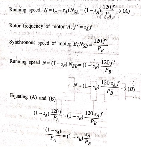
On no load SB=0
and the above eqn becomes
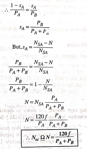
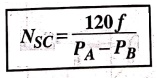
Differential
Cascade
In this case, the
rotating magnetic fields of motors A and B are in opposite directions. i.e, the
phase rotation of stator field of A and B are opposing. This reversal of phase
rotation is obtained by inter‒changing any of its 2 leads.
In this case, the
synchronous speed obtained is
NSC
= 120f / [PA‒PB]
Basic Electronics and Electrical Engineering: Chapter 5: Induction Motors : Tag: Basic Engineering : - Speed Control of Induction Motors
Basic Electronics and Electrical Engineering: Chapter 5: Induction Motors
Under Subject

Basic Electronics and Electrical Engineering
EE25C04 1st Semester ECE Dept | 2025 Regulation | 2nd Semester 2025 Regulation
Related Subjects

English Essentials I
EN25C01 1st Semester | 2025 Regulation | 1st Semester 2025 Regulation

தமிழர் மரபு - Heritage of Tamils
UC25H01 1st Semester | 2025 Regulation | 1st Semester 2025 Regulation

Applied Calculus
MA25C01 Maths 1 M1 - 1st Semester | 2025 Regulation | 1st Semester 2025 Regulation

Applied Physics I
PH25C01 1st Semester | 2025 Regulation | 1st Semester 2025 Regulation

Applied Chemistry I
CY25C01 1st Semester | 2025 Regulation | 1st Semester 2025 Regulation

Makerspace
ME25C04 1st Semester | 2025 Regulation | 1st Semester 2025 Regulation

Computer Programming C
CS25C01 1st Semester | 2025 Regulation | 1st Semester 2025 Regulation

Computer Programming Python
CS25C02 1st Semester | 2025 Regulation | 1st Semester 2025 Regulation

Fundamentals of Electrical and Electronics Engineering
EE25C03 1st Semester | 2025 Regulation | 1st Semester 2025 Regulation

Introduction to Mechanical Engineering
ME25C03 1st Semester | 2025 Regulation | 1st Semester 2025 Regulation

Introduction to Civil Engineering
CE25C01 1st Semester Civil Department | 2025 Regulation | 1st Semester 2025 Regulation

Essentials of Computing
CS25C03 1st Semester - AID CSE IT Department | 2025 Regulation | 1st Semester 2025 Regulation

Applied Physics I Laboratory
PH25C01 1st Semester practical Laboratory Manual | 2025 Regulation | 1st Semester Laboratory 2025 Regulation

Applied Chemistry I Laboratory
CY25C01 1st Semester practical Laboratory Manual | 2025 Regulation | 1st Semester Laboratory 2025 Regulation

Computer Programming C Laboratory
CS25C01 1st Semester practical Laboratory Manual | 2025 Regulation | 1st Semester Laboratory 2025 Regulation

Computer Programming Python Laboratory
CS25C02 1st Semester practical Laboratory Manual | 2025 Regulation | 1st Semester Laboratory 2025 Regulation

Engineering Drawing
ME25C01 EEE Mech Dept | 2025 Regulation | 2nd Semester 2025 Regulation
Basic Electronics and Electrical Engineering
EE25C04 1st Semester ECE Dept | 2025 Regulation | 2nd Semester 2025 Regulation